Whether you go with a PI, L, or T filter after the rectifier will depend on the amount of current and voltage you want. If you begin your filter stage with an inductor, you'll end up with less voltage and more current capability, even with the same transformer.
Start with the amp circuit and work backwards. Which Aleph were you interested in building? This will give you a target voltage and current draw. From there, you can begin to look at likely transformers and filter designs.
Grey
Start with the amp circuit and work backwards. Which Aleph were you interested in building? This will give you a target voltage and current draw. From there, you can begin to look at likely transformers and filter designs.
Grey
Thank you for the replies!
Im building a pair of aleph 2 monos. The transformers i have got are 800VA 33V Toroids.
Should i do any changes to the circuit?
Wuffwaff, i tested the program didnt understand much sorry )=D
Grollins. I dont know how big the voltage drop would be if i set the inductor at the begining.
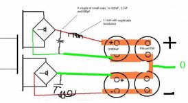
But if i have a package of different small caps before the inductor, does that lower the loss of voltages?
/kasra
Im building a pair of aleph 2 monos. The transformers i have got are 800VA 33V Toroids.
Should i do any changes to the circuit?
Wuffwaff, i tested the program didnt understand much sorry )=D
Grollins. I dont know how big the voltage drop would be if i set the inductor at the begining.
But if i have a package of different small caps before the inductor, does that lower the loss of voltages?
/kasra
I belive the purpose of the small input cap before the inductor is to keep the rectífier from beeing killed by back EMF in the coils and help reduce the current spikes that the PS otherwise would draw?
why not:
smalcap---inductor----largecap---inductor---large cap---Aleph
Btw i think this has been coverd severalt times before. In thread " PS for aleph 2" or something similar.
When using a cap you will get the peak of the sine wave i.e 1,414 and when using a coil the effectiv value i.e 0,9 ?
/micke
Hifi, as you know i havent got room for that last inductor.
What would the difference be between the one you described and a similar without that last inductor when it comes to that sine wave multiplier number? =D
Hifi:
Perhaps i can use those 1.8mH siemens blue ones between the caps?
/kasra
What would the difference be between the one you described and a similar without that last inductor when it comes to that sine wave multiplier number? =D
Hifi:
Perhaps i can use those 1.8mH siemens blue ones between the caps?
/kasra
Aleph supply
 Hi.If I were you i would try a voltage follower as the one proposed by Nelson in the part 3 of the Zen Variations.If you have enough transformer voltage to afford the 7V loss,then you should try it.I believe you would get no audible hum due to power ripple.
If you have not enough space for the inductors try it.Or if the voltage of the transformer is a bit low to afford it,then do only the version without the zener diodes.You would get a 4V loss and the supply will not be regulated,but should take away most of the ripple.
Try it and tell me if it works narshornsyst@hotmail.com
Hi.If I were you i would try a voltage follower as the one proposed by Nelson in the part 3 of the Zen Variations.If you have enough transformer voltage to afford the 7V loss,then you should try it.I believe you would get no audible hum due to power ripple.If you have not enough space for the inductors try it.Or if the voltage of the transformer is a bit low to afford it,then do only the version without the zener diodes.You would get a 4V loss and the supply will not be regulated,but should take away most of the ripple.
Try it and tell me if it works narshornsyst@hotmail.com
Kasra,
I´m not an expert in this subject,
but I would put the inductors between the large Rifa caps and I would paralell all the large caps with, for instance, a 10-100 uF SCR/Solen.
This configuration would give you max. voltage (and good sound I guess).
Accordingly to my high voltage tube experience the RIFA PEH 169 is not a very good sounding cap. Perhaps it is better for low voltage operation or you may have a different opinion that I have.
Good luck!
If you have a large cap at the input it will draw current spikes when it recharges (the smal time when the voltage over the cap is lower then the woltage from the rectifyer) this will produce a lot of HF noice on the powerlines not to good..
so why not try to prevent these spikes from the begining rather then try to filter them out with extra LC Stages?
/micke
so why not try to prevent these spikes from the begining rather then try to filter them out with extra LC Stages?
/micke
Siemens Capacitors
I think that this link can explain everything about PowerSupply
http://www.tnt-audio.com/clinica/ssps3_e.html
Part 1
Part 2
Part 3
Hope this clears things out
I think that this link can explain everything about PowerSupply
http://www.tnt-audio.com/clinica/ssps3_e.html
Part 1
Part 2
Part 3
Hope this clears things out
- Status
- This old topic is closed. If you want to reopen this topic, contact a moderator using the "Report Post" button.
- Home
- Amplifiers
- Pass Labs
- Aleph powersupply design question