well, thanks to some help from Magura, i have successfully powered on my aleph3. it doesnt smoke, everything looks ok, but there is no music. the speaker makes a hum (not really quiet, but not loud either. almost thought it was the transformer REALLY humming, but its the speaker). my rails are (under load) at around 22.5v or so. when they first switch on, its around 25-25, but then drops down a bit.
the thing that concerns me the most is that only one heatsink is getting warm... (i have two heatsinks, two transistors per sink). only one gets hot. the other gets warm, around 10F above room temp, but the other gets around 40F above room temp. not too hot to touch, but for sure warm. i didnt know if this is normal or not?
the transistors are matched, they are from my aleph2 project, so i have TONS of matched ones. i checked all connections and values for parts, they all appear fine. the light on the amp powers on, and nothing pops. (im using KRISTIJAN's boards, http://web.vip.hr/pcb-design.vip/aleph-3.html ).
hum, what else could i say to help out... OH, ive got my ground connected to the caps (using 2 26,000uf caps for testing), then to ground of rca input, and ground to speaker post. i tried connecting it to the ground pin on power cord, but didnt make a difference.
also, on the output of my source (its actually the headphone jack on a cd player with a volume knob), the volume does NOTHING to the level of the buzz. i can go from min to max and the buzz is the same. also, plugging and unplugging the source doesnt do anything, there isnt even a pop or a snap, so its like there isnt even an input.
any help is appreciated. i can take pics (albeit pretty low res), if it helps. its kinda a mess though, its all hooked up with alligator clips right now because the case is in the mail.
edit:
i am using a 250va transformer with dual 18v secondaries, into two 35a/600v bridge rectifiers, into two 26,000uf caps (for now), then into amp.
The easy solution to that is to start measuring the two sides and comparing them. Once you know where there is a difference, you will have some sort of guideline to get further.
A silly problem ive seen before is that the amp actually dont get any input signal. So to begin with id check the input side...does the amp actually get a signal?
Magura")
A silly problem ive seen before is that the amp actually dont get any input signal. So to begin with id check the input side...does the amp actually get a signal?
Magura
its all hooked up with alligator clips right now
until today i do not really understand why, but when i built Zen V4 it did not work but smoked resisors and did HF oscillation wired with alligator clips. It did work ok with thick copper wires soldered instead of the clips.

so, today do you understand why then?
i might have to try that out...
i might have to try that out...
till said:
until today i do not really understand why, but when i built Zen V4 it did not work but smoked resisors and did HF oscillation wired with alligator clips. It did work ok with thick copper wires soldered instead of the clips.
If the two sides are not the same temp, then they are not burning the same watts. That means you likly have a considerable offsett (dc voltage across the speaker terminals)
If the pos half is hotter, you likely have a problem in the signal side(neg half) like shorted output fet or input stage problem.
If the neg half is hot, the current source is likely current limiting the neg side and has a problem.
If you have a scope, a check of the outputs could tell if it's oscilating. I had a problem with my minialeph headphone amp where the input pair was oscillating, but the outputs didn't and you couldn't hear it (500,000 hz) but it made the thing sound muddy and undefined.
If it gets hot and the input has no effect on the output, I would first check for the correct voltages in the input current source and diff pair. Mosfets are quite fragile outside of their circuits.(static can kill one without you knowing)
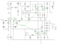
DC offset, Take a volt meter attach one end to the output the other to ground.
Measure from one side to the other of the sourcre resisters. This will tell you the current flowing though your output MOSFETS.
The drop across the 392 ohm resister Lets you know if Q1 is biased properly.
It's a start.
Measure from one side to the other of the sourcre resisters. This will tell you the current flowing though your output MOSFETS.
The drop across the 392 ohm resister Lets you know if Q1 is biased properly.
It's a start.
cowanrg said:MikeW,
well, measuring DC offset across the speaker terminals (output and ground), was 17V!!!!
i know enough to know thats not good.
You can say that again
for what it's worth, all the transistors were stored for some time. im not 100% sure if something happened to them, shock, static, etc... during that time. if there was an easy way to test them, it might be worthwhile. if that sounds like what's wrong, i have 10 sets of all of them from the aleph2 project... i literally have boxes of stuff, enough to make 10 or more alephs
well, as an update, i realized that T1 ,T2, and T3 (the IRF9610's) were not matched! i dont know what happened, but it looked like i just grabbed some out of a bag and slapped them in.
so now, they are matched. my fets are much closer in voltage now, the ones on the negative rail are a bit higher than the ones on the positive rail. they are around 15v for the negatives and 14v for the positives.
im getting a current draw of over 3 amps, which is high. not to mention, i am also still getting 8v dc offset, still very bad.
i tested the voltage drop across across R108, the 390ohm resistor, and im getting a drop from 20v down to 14.93, so 5.03V. the service manual says 4-5v. im not sure of the tolerances i should be looking at... but it seems close.
does anyone have any ideas? Magura has been doing his best to help me out (he is a real help to this forum, contrary to what some people think), but our time zones are a bit different.
i have 3 more faceplates left over! just kidding, you would have to pry those off my dead body!
Alain,
i will try and measure all the points you mentioned. I am VERY new to all this. I can solder and build things, but im not great around a meter yet.
EDIT: the transistors were measured and matched a LONG time ago. i got them on this forum from a group buy maybe 1.5 years ago. i cant even remember who i got them from
MikeW,
As mentioned above, im kinda new to all this. i am not sure how to do what you are saying... if you could explain what you mean like you would an idiot, i can definately measure.
- Status
- This old topic is closed. If you want to reopen this topic, contact a moderator using the "Report Post" button.
- Home
- Amplifiers
- Pass Labs
- bringing up aleph 3, no smoke, but no sound