A lot depends on the switch you are considering. A low amperage switch can easily be used to control a triac. One possible issue is how the illumination works. If the LED/bulb has external connections then there is no problem. If it is internal to the switch and is mains rated then things would get more complex.
One important point is that any switch used MUST meet relevant standards for insulation as the switch is still live at all times.
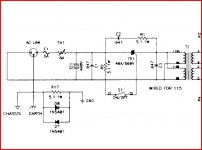
Nelson used just such a simple design here. A small switch and resistor plus a Triac and snubber.
One important point is that any switch used MUST meet relevant standards for insulation as the switch is still live at all times.
Nelson used just such a simple design here. A small switch and resistor plus a Triac and snubber.
Attachments
This little board works very well:
The ε24 power switch driver circuit
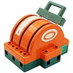
Along with this transformer:
The σ24 power transformer board
The ε24 power switch driver circuit
Along with this transformer:
The σ24 power transformer board
Being idle, this is what I used.
Works very well.
LED Driver Power Supply Transformer 240V - DC 12V | eBay
Works very well.
LED Driver Power Supply Transformer 240V - DC 12V | eBay
Please don't be so angry, Pat ")
I might have a new, or at least in box unit similar to this, but not exactly this:
NCC, NATIONAL CONTROLS CORPORATION TIME DELAY RELAY Q1T-00300-341, 120 V | eBay
I recall it has a 3 sec min adjustable delay and needs a low current 120vac to trigger the box. The time delay is a nice way to figure in a soft start. Worked mint on a Krell Klone I did
PM me if you're interested, I'm not greedy
*Self-locking momentary action push to make connection - I think that means latching.
5~240V 16mm Car LED Power Push Button ON/OFF Switch Self-locking Latching Kits | eBay
5~240V 16mm Car LED Power Push Button ON/OFF Switch Self-locking Latching Kits | eBay
Mains switches, 250V / 5A:
https://www2.mouser.com/ProductDetail/506-AV1921P712Q04?r=506-AV1921P712Q04
European source, for example:
Elektronik, Technik, Werkzeug und mehr | voelkner - direkt gunstiger
These are available in different sizes, different number of switched poles, LED colors, and 12V or 24V LEDs.
- I typically use one of them directly as a mains switch, and a CL-60 in series after the switch as a soft start (as mentioned by Wayne above also).
- I use a two-pole switch to switch both hot and neutral, because in Germany we don't have keyed / polarized mains plugs ... that way, if the switch is in the off position, there is no voltage at downstream components, regardless of how the mains plug is oriented in the socket ...
- When using a 12V LED, I got the 12V by just tapping in the V+ line of the amp (24V), reducing to 12V via a simple resistive voltage divider.
Best regards,
Claas
P.S.: I actually wouldn't mind a big honkin' toggle mains switch in my next amp, one that makes a really big mechanical "klonk" ...
https://www2.mouser.com/ProductDetail/506-AV1921P712Q04?r=506-AV1921P712Q04
European source, for example:
Elektronik, Technik, Werkzeug und mehr | voelkner - direkt gunstiger
These are available in different sizes, different number of switched poles, LED colors, and 12V or 24V LEDs.
- I typically use one of them directly as a mains switch, and a CL-60 in series after the switch as a soft start (as mentioned by Wayne above also).
- I use a two-pole switch to switch both hot and neutral, because in Germany we don't have keyed / polarized mains plugs ...
that way, if the switch is in the off position, there is no voltage at downstream components, regardless of how the mains plug is oriented in the socket ... - When using a 12V LED, I got the 12V by just tapping in the V+ line of the amp (24V), reducing to 12V via a simple resistive voltage divider.
Best regards,
Claas
P.S.: I actually wouldn't mind a big honkin' toggle mains switch in my next amp, one that makes a really big mechanical "klonk" ...
.....wouldn't mind a big honkin' toggle mains switch in my next amp, one that makes a really big mechanical "klonk" ...
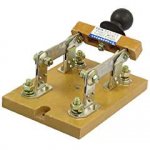
I use the Big Red Paddle switches for various things (not, so far, an amp).
The paddle comes off if you DON'T want a panic-stop.
Knife-switches are available from sub-toy to whole-factory. Even the "safe" ones probably should not directly switch power to an amplifier, but they can tickle a relay/triac. Most do not "klonk", not even my whole-house generator disconnect; that is the province of more expensive high-power types.
Attachments
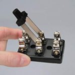
These will not turn off a PSU with a 300VA x'former more than once. Ask me how I know. 😉
George
These will not turn off a PSU with a 300VA x'former more than once. Ask me how I know. 😉
George
That switch is rated 5A at 250vac. For 110/120vac it would be rated closer to 2A.
In my F5Tv3 monos I used a very small 9v transformer (10va), which is always powered, to a small rectifier & smoothing cap via a similar type on/off button. The rectifier and cap voltage goes to the LED in the button and a 30A chassis mounted relay which switches the mains.
The button below is the one I ordered because it was in stock at the time. You only need SPST.
transformer AN-0109 - 10VA 9V Transformer - AnTek Products Corp
push button switch PV7F2T0SS-344 E-Switch | Mouser
chassis mounted relay T9AP1D52-12 TE Connectivity / P&B | Mouser
small rectifier GBU4D ON Semiconductor / Fairchild | Mouser
These will not turn off a PSU with a 300VA x'former more than once. Ask me how I know. ��
George
I am using these in various amps, 500VA transformer, dual 200VA transformers, ... No problems so far. But then I am on 230V ...
Best regards, Claas
Last edited:
That switch is rated 5A at 250vac. For 110/120vac it would be rated closer to 2A.
Maybe I have a hickup in my brain this morning, that sometime happens
... I don't see it at the moment, why should the switch have a lesser current rating at half the voltage ?Best regards,
Claas
Hmmmm ...
most data sheets for switches only specify max. current at 250V AC and low-voltage DC.
Where I find information on 125V AC as well, it is usually the same current as for 250V or higher.
See the following:
HS 636 H2: Hebelschalter, 10(4)A-400VAC, 1x Ein-Ein bei reichelt elektronik
Linked data sheet only in German, unfortunately, but you should get the gist...
All that said, what destroys a switch when switching off is arcing; at high currents the switch may not even be able to switch off the current flow as the arc is persisting...
This is mostly driven by current running through the switch.
Obviously, if you are switching a Class A amp, the current draw at 125V mains is higher than at 250V ...
An amp that consumes 200W (mostly in output stage bias and therefore in heat idling) draws a bit less than 1A at 250V mains, and a bit less than 2A at 125V mains.
Therefore, the current load that the switch has to switch off is higher at 125V than at 250V, but the current rating of the switch itself is not changing.
Maybe that is part of the confusion.
There may be an influence from the inductive load of the transformer, whose resistive component is lower for a 125V primary winding.
But this data sheet
HS 3531-02: Hebelschalter, 20A-125VAC, 1x Ein-Aus bei reichelt elektronik
doesn‘t show a reduction in current capability for inductive loads.
Also, it is good practice to put a small capacitor (commutation capacitor, is that the correct term ?) across the poles of the switch (between switch input and output) to help extinguish the spark when switching off, before it can become an arc ...
I usually use something like a 10nF PP there.
Does that make sense ?
Best regards,
Claas
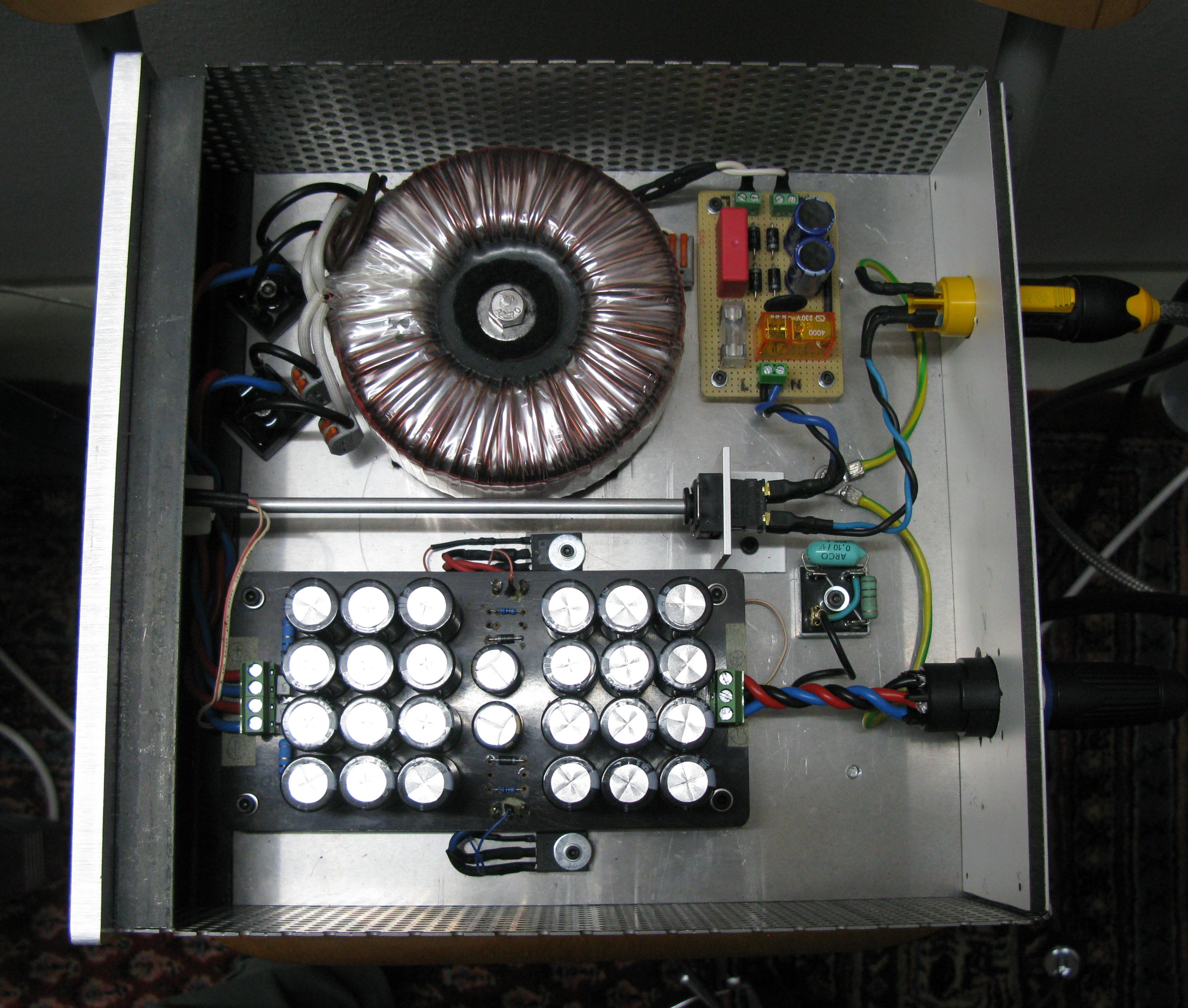
I for one am quite confident with the arcoelectric 8300 switch.
have used in all my later builds - not illuminated but 2pole 16A/230V
vandalproof. You can even separate the front-button from the switch as I did
in my M2 PSU.
A.
H8350RPAAA | Arcolectric Frontplatten Druckschalter, Ein-Aus, O 19.2mm, Schliesser 2-polig, 16 A, IP 66 | RS Components
have used in all my later builds - not illuminated but 2pole 16A/230V
vandalproof. You can even separate the front-button from the switch as I did
in my M2 PSU.
A.
H8350RPAAA | Arcolectric Frontplatten Druckschalter, Ein-Aus, O 19.2mm, Schliesser 2-polig, 16 A, IP 66 | RS Components
Attila, that's a nice switch. And a very clever implementation. Would you mind explaining a bit how you added the shaft?
Your switch is available at Newark in the US. I wish I had known of it when I was building my amp. I used the switch mentioned above. It failed on the second turn-off and I had to add a relay board and use the switch to control the relay.
George
- Status
- This old topic is closed. If you want to reopen this topic, contact a moderator using the "Report Post" button.
- Home
- Amplifiers
- Pass Labs
- Power Button