I've wanted to try a SUSY amp for years now... So, I decided to finally make one this summer to break the monotony.
Like the original UGS power amplifier, this is a compilation of several different circuit ideas. It is, of course, based on the original UGS-UP amplifier, which is itself based on Pass Labs' X-series of amplifiers. My goals were the following:
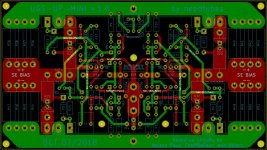
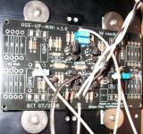
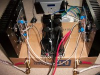
Attached are images of my boards and temporary test build. Circuit description to follow...
Like the original UGS power amplifier, this is a compilation of several different circuit ideas. It is, of course, based on the original UGS-UP amplifier, which is itself based on Pass Labs' X-series of amplifiers. My goals were the following:
- Up to 25W output, since we've seen quite often that this is sufficient for many listeners (including me).
- First few watts in Class A.
- Option to scale up the power output or Class A envelope by using larger MOSFETs or heatsinks (or both).
- Option for no source degeneration on output stage, as discussed in recent threads on the XA25, F4 Beast, DEF, etc.
- Option for local or global feedback loop.
- Option for resistor-based single-ended bias in any of the four quadrants, as used in Pass Labs XA*.5 series.
- Option to load one-half of the driver stage to tailor the distortion spectrum.
- Uses TL431 plus a thermistor to establish bias instead of a typical Vbe multiplier.
- Uses "current feedback" as implemented in the Sony VFET2 amp and many of Pass' recent offerings.
- Only two trimpots used to zero absolute and relative offset.
- Small-sized PCB to allow compact builds.
- Option to use the PCB to build a stereo amplifier instead of an X-amp.
Attached are images of my boards and temporary test build. Circuit description to follow...
Attachments
Last edited:
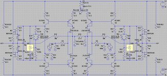
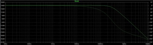
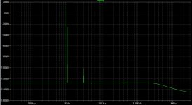
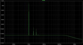
Schematic for the UGS-UP-mini and SPICE predictions (frequency response, FFT for circuit as pictured, and FFT with 10k resistor on negative phase driver stage) are attached. My measurement rig doesn't do balanced output, so I cannot measure the true performance of the amp. Some notes:
My heatsinks are around 5" tall by 9" long with 1.25" fins. This gives just enough dissipation for 1A bias per channel (so, 0.5A per phase) on ~16V rails with a 25C rise. One could, of course, scale up the heatsink size and increase the bias. Bias is rock solid, even with no source degeneration (as pictured).
And, lastly, the amp sounds great. Very detailed, clean sound from top to bottom, nice soundstage, although a little forward in its current configuration. Now to experiment with SE bias and different loads on the driver stage...
My thanks to Nelson Pass, CheffDeGaar, and others for inspiring the various pieces of this project.
- R35 is used for SUSY operation.
- R35a and R35b are used instead of R35 to create two separate channels on one board.
- R33 and R34 are option front-end load resistors to alter the THD spectrum.
- GR grade JFETs with IDSS around 5mA were chosen since I have these in stock. BL can be used with some changes.
- The thermistors should be in contact with the heatsink (mount on bottom of PCB).
My heatsinks are around 5" tall by 9" long with 1.25" fins. This gives just enough dissipation for 1A bias per channel (so, 0.5A per phase) on ~16V rails with a 25C rise. One could, of course, scale up the heatsink size and increase the bias. Bias is rock solid, even with no source degeneration (as pictured).
And, lastly, the amp sounds great. Very detailed, clean sound from top to bottom, nice soundstage, although a little forward in its current configuration. Now to experiment with SE bias and different loads on the driver stage...
My thanks to Nelson Pass, CheffDeGaar, and others for inspiring the various pieces of this project.
Attachments
Last edited:
The bias circuit comes from F4 but you can just as well use a Vbe multiplier.
It is not all FET anyhow, unless you change the current mirror BJTs to MOSFETs.
If you are not using NFB, then making R13,14 trimable will allow you to have slightlay different Vgs for P- and N-MOS.
Patrick
It is not all FET anyhow, unless you change the current mirror BJTs to MOSFETs.
If you are not using NFB, then making R13,14 trimable will allow you to have slightlay different Vgs for P- and N-MOS.
Patrick
See also (single-ended, simplified) :
http://www.diyaudio.com/forums/pass-labs/300060-pass-hpa-1-a.html#post4904225
(Post #10)
Patrick
http://www.diyaudio.com/forums/pass-labs/300060-pass-hpa-1-a.html#post4904225
(Post #10)
Patrick
What prompted the query...
I was just idly wondering really. I've seen quite a few variations in something close to this exact circuit from the gr25 double bjt, to the usual Vbe multiplier, to the f4 tl based option to Zen Mod's new hall effect/M2 bias. Needtubes called out the TL in particular and I was intrigued as to why?
ZM's recent effort is pretty cool.")
The bias circuit comes from F4 but you can just as well use a Vbe multiplier.
It is not all FET anyhow, unless you change the current mirror BJTs to MOSFETs.
If you are not using NFB, then making R13,14 trimable will allow you to have slightlay different Vgs for P- and N-MOS.
Patrick
I was just idly wondering really. I've seen quite a few variations in something close to this exact circuit from the gr25 double bjt, to the usual Vbe multiplier, to the f4 tl based option to Zen Mod's new hall effect/M2 bias. Needtubes called out the TL in particular and I was intrigued as to why?
ZM's recent effort is pretty cool.
Last edited:
The M2 bias is self biasing. No adjustment required.
But you have to have a certain voltage across the source resistors for the optocoupler to work.
It might be a limitation (design constraint) that you do not want.
The TL431 is stable and does not drift with temperature, as a Vbe multiplier does.
But for my taste it is rather noisy, unless you use the On Semi version and bypass one of the resistors.
The right BJT can be very low noise, and it has a negative tempco.
Since most FETs has a positive tempco, so the reduced bias voltage of a Vbe multiplier might not be a bad thing.
Or you just use two resistors and trim them both for bias AND offset.
This is especially useful with lateral FETs as they have a negative tempco and hence self stabilise.
UTHAiM -- Just for Fun
But, just my personal opinion.
Patrick
See also (single-ended, simplified) :
http://www.diyaudio.com/forums/pass-labs/300060-pass-hpa-1-a.html#post4904225
(Post #10)
Patrick
Thanks! And great documentation too. Now I'm reading up about cascoding current mirrors... So thanks again!
May I ask why the choice of the bias circuit? As opposed to any of the other options?
As EUVL pointed out, the TL431 bias circuit essentially comes from the F4. Generg successfully used a variation with thermistors in his F4 Beast, so I opted to do the same since I wanted to try the circuit without source degeneration.
Would it be easy to allow for a separate front end regulator as in cheffs ups amp?
Yes and no... The boards I designed don't allow for this, since my goal was to simplify the build as much as possible. But, one could certainly design it in, at the cost of having to use higher overall voltage rails or two separate voltages for input and output stages.
Ditto, I'm only half done with the PCB layout.Nice project! I've been considering doing something similar, but... All I've done is thought about it!
Sign me up for boards if and when available.
With a little modification, it could be the ultimate universal PCB, UGS UP to Sony V FET front via BA3(B), F5(T&X) etc.
If there is a wish list, option for a cascoded current mirror please.
And only 1 PCB for the store to stock.
And only 1 PCB for the store to stock.
That would be pretty neat.
One board to rule them all?
After building the Borbely EB602 and comparing against essentially identical V-MOS versions, I have to agree with Erno.
Lateral FETs just sound better, unless you only want lots of bass.
The Borberly EB602-200 Revisited
So if I have to use this topology (single-ended, i.e. not balanced), I would just build the UTHAiM power amp.
UTHAiM -- Just for Fun
(Post #11)
Patrick
Lateral FETs just sound better, unless you only want lots of bass.
The Borberly EB602-200 Revisited
So if I have to use this topology (single-ended, i.e. not balanced), I would just build the UTHAiM power amp.
UTHAiM -- Just for Fun
(Post #11)
Patrick
Last edited:
I very seriously considered using laterals. In fact, my original layout was for laterals. Ended up with the usual IRF parts because I have a couple hundred of them in stock already measured for Vgs. Plus, they are cheaper and generally easier to obtain.
I do look forward to trying amps like this with laterals some time down the road when I can justify the cost.
I do look forward to trying amps like this with laterals some time down the road when I can justify the cost.
Read the review in Post #4 of the EB602 thread, and the Didden interview :
https://linearaudio.nl/sites/linearaudio.net/files/BorbelyAnnalsMMM508.pdf
Patrick
https://linearaudio.nl/sites/linearaudio.net/files/BorbelyAnnalsMMM508.pdf
Patrick
Sign me up for boards if and when available.
Well, I have several boards left over from my initial run, if you are interested in trying the amp as presented in the first two posts.
With a little modification, it could be the ultimate universal PCB, UGS UP to Sony V FET front via BA3(B), F5(T&X) etc.
If there is a wish list, option for a cascoded current mirror please.
And only 1 PCB for the store to stock.
This was my original project idea - large output boards for the 5u UMS heatsinks with plug-in driver board so that I could try different front ends. Sounds like Mr. Pass may have this in the works for the DIY store (see AB100 thread), so I decided to try out the "down-sized" version instead for some summer fun while we wait for his offering. Just happened to coincide with a need for a smaller, cooler running amp.
Well, I have several boards left over from my initial run, if you are interested in trying the amp as presented in the first two posts.
This was my original project idea - large output boards for the 5u UMS heatsinks with plug-in driver board so that I could try different front ends. Sounds like Mr. Pass may have this in the works for the DIY store (see AB100 thread), so I decided to try out the "down-sized" version instead for some summer fun while we wait for his offering. Just happened to coincide with a need for a smaller, cooler running amp.
May I take you up on that? I've a small spare chassis that might be ideal and some large 15V secondaries transformers... And plenty of smoothing caps, so this might be a fun quick project for me.
- Status
- This old topic is closed. If you want to reopen this topic, contact a moderator using the "Report Post" button.
- Home
- Amplifiers
- Pass Labs
- UGS-UP-Mini: A 25W SUSY Amp