It might be interesting to start a H2/H3 spreadsheet.
Two sets of post adjustment values.
1. H2 H3 adjusted to a pre determined ratios and phase. note the dc offset voltage at the junction of R3 & R4.
2. P3 adjusted to personal taste, note H2 H3 values, that would be interesting in it's self.
In all cases, note the idss; if there is enough data, patterns may emerge.
Sounds good, I know nothing about spread sheets.
Russellc
...about to buy one...
If you have a PC, see ZM's post #68
EMU1212
Apologies, I'm not familiar with the various model numbers, I should do some research before posting.
no need for apologies , at all
EMU1212 is good drek , but unnecessary complicated for regular hobbyist , outside of sound production
If you have a PC, see ZM's post #68
I searched for it, "no longer available" I am inquiring about the Focusright 212....it is confusing, but I'm determined to get busy with it and adjust me some P3.
Russellc
FocusRite 2i2 2nd gen USB Audio Interface, works well for me. The output can be used as a low-distortion signal generator also.
This interface has been recommended by 6l6 in another thread.
Best regards, Claas
Is the focusrite 212 a sound card as well?
Russellc
Yes the 2i2 is a proper sound card which is connected via USB. But performs the same basic functions as a PCI or pcie sound card. The main advantage of going with USB is that it is portable and can be used with a laptop.
There are some things I prefer about using a pci card (I find the gain knobs on the 2i2 really finicky to adjust), but the portability and being able to use a laptop running off battery are the main reasons I went with a 2i2.
edit: the main advantage of using a laptop (apart from portability) is that you can completely eliminate the PC as a source of ground loops.
Tony.
Last edited:
Yes the 2i2 is a proper sound card which is connected via USB. But performs the same basic functions as a PCI or pcie sound card. The main advantage of going with USB is that it is portable and can be used with a laptop.
There are some things I prefer about using a pci card (I find the gain knobs on the 2i2 really finicky to adjust), but the portability and being able to use a laptop running off battery are the main reasons I went with a 2i2.
edit: the main advantage of using a laptop (apart from portability) is that you can completely eliminate the PC as a source of ground loops.
Tony.
Thanks, I am beginning to understand more and more about this setup!
Russellc
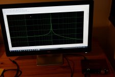
I had my first play with 2i2 and ARTA software. A loop back test with a 1k sine. Fs = 48k and FFT = 131072. It looks very clean. No 2nd and 3rd harmonic which of course is good for a test sine generator. But it looks a little to good to be true?
If I turn up the signal so the green ring goes red......then I got a lot of distortion…..as expected.
What is a good value for FFT?
The number is the resolution? …..higher number better?
The recording takes longer if FFT is high.....which probably is logic.
There is a steep learning curve……...….
If I turn up the signal so the green ring goes red......then I got a lot of distortion…..as expected.
What is a good value for FFT?
The number is the resolution? …..higher number better?
The recording takes longer if FFT is high.....which probably is logic.
There is a steep learning curve……...….
Attachments
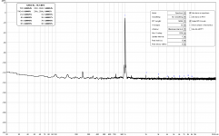
Hmm to me it looks like your noise floor is quite high at -80'ish. Maybe lower preamp gain and turn up your output dial. Did you use smoothing? Here is a loopback from my Mbox3 for comparison. Master volume all the way up (as i think Wintermute mentioned) and preamp around 10-11 o'clock.

That's the lowest distortion i could get. Using balanced cables made no difference, and disconnecting the sleeve from the jack (or corresponding pin on XLR) actually gave me increased distortion.
You should be able to go lower for FFT length, 16 or 8k. I don't think it is a critical parameter, just makes measurements faster (with lower values).
Attachments
Last edited:
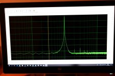
Ok.....I tried again by setting the sine generator to -6 dB and set monitor to max. and then input gain to approx. 11 o'clock. But what did the real trick was to change Wnd from Uniform to Hanning. Avg set to linear. I have 0 dB at top and noise floor is now close to -130 dB. Now it looks more realistic with some 2nd and 3rd harmonic. One should think that output of sine generator will give best result if set to 0 dB for max. resolution in the DAC?
Will play more with that…….
Will play more with that…….
Attachments
It was just a loop back test......so output back to input to check how ARTA works and also get a feeling for how clean the built-in test generator is.Glad to see you getting somewhere with your setup! What was your device under test? A BA3 FE?
Russellc
I wonder if it is possible to work with an external test generator in such a setup with ARTA.
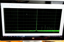
By playing a bit with the settings in the loop back test I was able to get the noise floor just under -140 dB and 3rd harmonic which is the most dominant below -100 dB. All other harmonics are well below -100 dB. Is this considered a quality sine that can be used for testing preamps? ….would I be able to adjust P3 using such a setup? ….it will require that the distorsion of the test generator is much lower than the distortion pattern of the BA3 pre?
Attachments
- Home
- Amplifiers
- Pass Labs
- P3 Adjustment for the average Hobbyist