I found this.
Sound card probe? Looks like a schematic even I can understand.
Thanks,
Russellc
Interesting you are getting very good distortion performance with the TS loopback cable! Is yours a second gen 2i2? I'll have to try with 48Khz sampling, I've only been testing with 96Khz...
I assume you increased the gain on the preamp when using the attenuator to get the same -3db reading. Try doing it again with arta showing -9db and the performance may be better. I noticed that both the input gain and the output level affect the distortion even when within limits.
Tony.
Yes, 2nd gen 2i2.
I just used standard TS-TS cable for loopback, didn‘t try a different configuration yet.
Also, input was set to Line. Inst was much worse, using Mic with an xlr connector was actually better than Inst , but a bit worse than Line.
I experimented with output level and input preamp gain in combination. When I did raise output level to more than about 2 o’clock (don’t remember the absolute level and can’t look up at the moment), distortion rose. So that’s where it stayed, and adjusting input preamp gain to -3 dB level overall in loopback scenario gave best distortion and noise performance.
Tony, you’are probably right that at least part of what I’m seeing with the attenuator is due to re-upping the level to -3 dB by raising input preamp gain, and thereby raising the noise floor.
I’ll have to try with constant input preamp gain when I’m back home, though I think I had some issues with noise-vs.-distortion performance in that case.
Also, I think there is some noise pickup by my attenuator. Look at the 50 Hz and harmonics, when I had no connection to the power line (battery-operated Thinkpad S440).
Best regards, Claas
Last edited:
Russelc, I think the 2i2 or any decent USB (or pci) sound card will do just fine. typical distortion of the cards is 0.001% or better, what you are measuring will likely be 0.01% or worse. So there is plenty of margin there. That attenuator that El Reino posted looks interesting, but I'm going to have to sim it because I'm having a bit of trouble working out the voltage divider. I'm not sure if it is a stereo setup or a single channel balanced...
Tony.
Tony.
Thanks Claas, I used to also only raise the volume knob to perhaps 3 o'clock but now for repeatabilities sake I move it all the way to 100% and just use the output level in Arta (or holm impulse/rew depending on what I am using) to adjust the output levels (I think it is comparible).
It looks like from your testing that they have modified the input circuitry of the 2nd gen to not have the issues my first gen has with ring being shorted to sleeve.
50Hz noise pickup has been the biggest problem I have faced. I get it too running off battery testing stuff that has no mains connection. It seems to be airborne. Better shielding and testing outside help.
Tony.
Russlelc, looking some more at that attenuator I think it is for a stereo setup. I don't believe it has enough attenuation for measuring power amps, and I think you need something more along the lines of what was posted earlier with either LED's or zenners for clamping as a safety measure.
The thought of using a pot as part of the voltage divider for variable attenuation is nice though. I think changing the values to 22k for both resistors (giving a minimum cut of 6db) and the pot to 200K would give a much better range for power-amp testing, I wonder about the longevity of the pot, but I guess with 22K minimum, the current will be low. I might do some experiments with a setup like this. It would be important to always start with the pot in the max position. Some clamping diodes would be wise.
Tony.
Russlelc, looking some more at that attenuator I think it is for a stereo setup. I don't believe it has enough attenuation for measuring power amps, and I think you need something more along the lines of what was posted earlier with either LED's or zenners for clamping as a safety measure.
The thought of using a pot as part of the voltage divider for variable attenuation is nice though. I think changing the values to 22k for both resistors (giving a minimum cut of 6db) and the pot to 200K would give a much better range for power-amp testing, I wonder about the longevity of the pot, but I guess with 22K minimum, the current will be low. I might do some experiments with a setup like this. It would be important to always start with the pot in the max position. Some clamping diodes would be wise.
Tony.
Did you have a look at this one?
Electronic Equiptment - DIY soundcard scope probe
It was suggested by vdi_nenna and 6L6.
Russellc
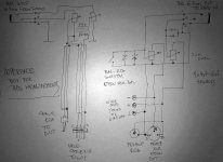
EMU1212 bal out , bal cable to box
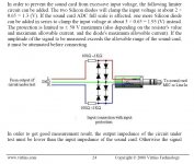
bal 6.3mm female on box , to 22K bal pot attenuator , then RCA on cable to DUT (taken + as hot and gnd ) , also XLR on cable to DUT , obviously taken both hots and GND to
you choose which cable goes to DUT , second one unused
then , again in box , in parallel (logically connected) RCA and XLR and 4 wire-screw connectors (two gnds , one + and one - hots) , leading to 22K bal pot attenuator , then to bal 6.3mm female , then bal cable to EMU1212 input ;
at that last pot connected switch for grounding negative hot , for RCA (unbal) tests
pics enclosed , some of procedure explained in Babelfish M25 , AKA M2 on steroids , AKA M2-XA25 bstrd
anti series , or anti parallel zeners (say 6V8 to 7V5) connected between second pot wipers and gnd , as soundcard input protection ; you'll not see them in pic of course

procedure is - all levels all the way up on EMU (ARTA help will tell ya) , first pot sets needed input level to DUT (say that you're shooting at 1W/8R , some amp ; whatever goal it is - you need to observe that with scope)
crocodile clip thingies from amp out to 4screws thingie on box , switch to RCA (grounded neg leg on EMU input) , level to EMU set with second pot (look at desired dBFS figure)
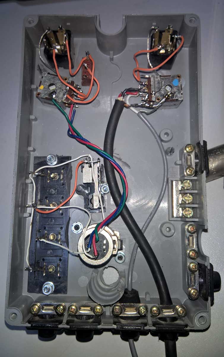
use metal box , short cabling , do not use autoformers if you want blameless measurements
tricky to draw all these connectors in any program I have in my PC , scanners ....... 3 of them , none working at wcrap 7 , lazy to bring 4-th , so I can scan back of napkin schm
just look at pictures
and yes: 6.3mm jack - tip is + hot , ring is - hot , sleeve is gnd
bal 6.3mm female on box , to 22K bal pot attenuator , then RCA on cable to DUT (taken + as hot and gnd ) , also XLR on cable to DUT , obviously taken both hots and GND to
you choose which cable goes to DUT , second one unused
then , again in box , in parallel (logically connected) RCA and XLR and 4 wire-screw connectors (two gnds , one + and one - hots) , leading to 22K bal pot attenuator , then to bal 6.3mm female , then bal cable to EMU1212 input ;
at that last pot connected switch for grounding negative hot , for RCA (unbal) tests
pics enclosed , some of procedure explained in Babelfish M25 , AKA M2 on steroids , AKA M2-XA25 bstrd
anti series , or anti parallel zeners (say 6V8 to 7V5) connected between second pot wipers and gnd , as soundcard input protection ; you'll not see them in pic of course
procedure is - all levels all the way up on EMU (ARTA help will tell ya) , first pot sets needed input level to DUT (say that you're shooting at 1W/8R , some amp ; whatever goal it is - you need to observe that with scope)
crocodile clip thingies from amp out to 4screws thingie on box , switch to RCA (grounded neg leg on EMU input) , level to EMU set with second pot (look at desired dBFS figure)
use metal box , short cabling , do not use autoformers if you want blameless measurements
tricky to draw all these connectors in any program I have in my PC , scanners ....... 3 of them , none working at wcrap 7 , lazy to bring 4-th , so I can scan back of napkin schm
just look at pictures
and yes: 6.3mm jack - tip is + hot , ring is - hot , sleeve is gnd
Last edited:
Yes it is another interesting option providing DC protection (with the cap) and from 0db to infinite attenuation, but no over-voltage protection. A couple of back to back 3V zenners on the output would be a good safety addition I think. A bipolar electro rather than a polarised one would also be a good idea, as you can't tell whether the offset on the amp output would likely be +ve or -ve.
Tony.
Tony.
")
started drawing it in paint , you'll get it tonight here
Thanks a million. Cant say I am not pleased as punch at the response here. Guess I wasnt the only one wondering what could be with P3, but were not well enough versed to figure it out. I am learning as we go, and am excited about prospect of actually adjusting P3 to advantage!
Thanks,
Russellc
damn Paint
finally took back of napkin approach , phone cam and Photoshop
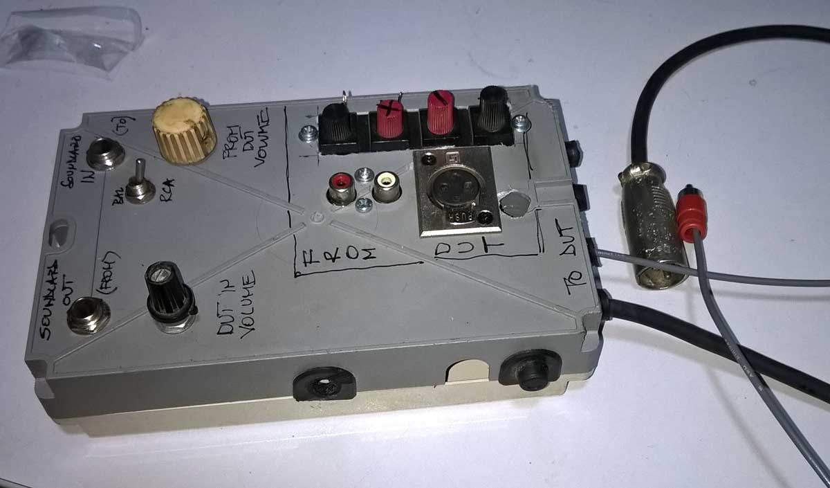
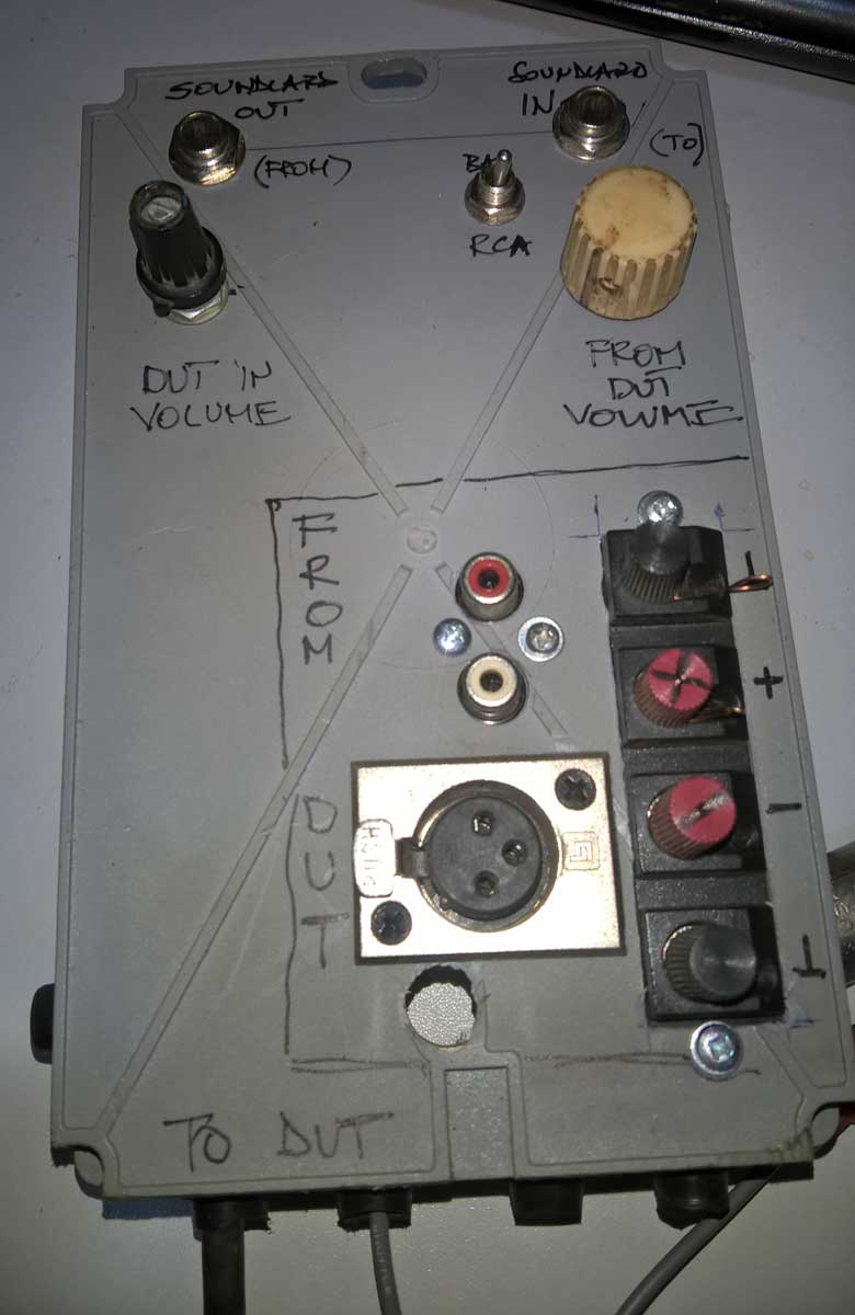
Steel (box), ZM , Steel !!!
just to have it handy :
6.3mm bal connection : sleeve GND , tip + phase, ring - phase
XLR connection : pin 3 GND , pin 1 - phase , pin 2 + phase
finally took back of napkin approach , phone cam and Photoshop
Steel (box), ZM , Steel !!!
just to have it handy :
6.3mm bal connection : sleeve GND , tip + phase, ring - phase
XLR connection : pin 3 GND , pin 1 - phase , pin 2 + phase
Attachments
Last edited:
Now for real embarrassing display of ignorance....These drawings represent connection to device under test, from device under test to and from what ever interface, 212, whatever.
Then, connection from interface to computer w ARTA, REW, whatever by some other connection? Or do I have that all mixed up to? Probably need to stare at your pics a while too.
Yup, babe in woods here for this stuff! Sorry.
Russellc
Then, connection from interface to computer w ARTA, REW, whatever by some other connection? Or do I have that all mixed up to? Probably need to stare at your pics a while too.
Yup, babe in woods here for this stuff! Sorry.
Russellc
Last edited:
Yes, USB.... connection from interface to computer w ARTA, REW, whatever by some other connection? ...
Yes, USB.
Thanks...one more question, for now. Is this the schematic for device used by zenmod in Babelfish M25 , AKA M2 on steroids , AKA M2-XA25 bstrd thread? Or slightly different?
Thanks for everyone's patience.
Russellc
- Home
- Amplifiers
- Pass Labs
- P3 Adjustment for the average Hobbyist