Yes, the two input connectors on the front are combined jack and XLR connectors. The XLR is for microphone and the jack is either for an instrument or a line source. There is a switch which configures the jack input to either an instrument (2-pole, TS) or line (3-pole, TRS) jack. Something I do now know much about so first thing is to find out how to make the physical /electrical connection from the e.g. preamp to an e.g. jack connection. I assume that it is the jack connection that should be used and maybe the instrument settings (two pole jack) is the most easy to adapt to (if the output from e.g. preamp is normal RCA out (non-balanced). If balanced the line setting (balanced) is probably the way to go.
Last edited:
Maybe something like this can be used as adapted for instrument input mode to RCA:
6.3mm Mono Jack Male to RCA/Phono Female Audio Adapter - from LINDY UK
6.3mm Mono Jack Male to RCA/Phono Female Audio Adapter - from LINDY UK
MEPER I do not think you can use the instrument setting. I believe that is a high sensitivity input and you will likely overload the input if you switch it to instrument. I would have to test (with very low output) to verify though.
You can use a mono plug for input but you will be limited to the SE performance that I posted above.
Ideally if you want best results testing SE equipment (ie lowest distortion introduced by the sound card itself), you need a balanced to SE converter on the output and an SE to balanced converter on the input.
Tony.
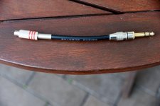
So an adapted like this could work in "line" setting?
Monoprice 1/4in (6.35mm) TRS Stereo Plug to RCA Jack Adapter, Gold Plated - Monoprice.com
Monoprice 1/4in (6.35mm) TRS Stereo Plug to RCA Jack Adapter, Gold Plated - Monoprice.com
...fully differential the distortion performance is very good. But if running single ended the distortion goes up significantly...
Looks like opamp time, would you need anything better than a TL07x for a s/e to bal converter (& visa versa) (1Khz @ 2Vrms)? I cant remember the unity gain distortion figures, was it decimal two or three zeros? recommendations anyone?
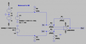
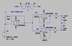
These are the circuits I have bread boarded (though I need to revisit, as I pulled it out and was not able to reproduce my previous results). I'm going to make up some new cables as well as I think perhaps the main issue is to keep either of the differential inputs from being connected to the shield, and a passive option may be possible.
The Balanced to SE I originaly used 2K resistors for {RES} thinking I needed low values to keep the noise floor low, however I think I tested with 10K and it made virtually no difference (noise floor still below -120db)
With the SE to Balanced circuit 10K also worked fine (though for some reason I had 6.8K in spice... i think I was trying to find the sweet spot for lowest IM distortion in the sim).
Both circuits I bread boarded with 100nf decoupling caps on the IC's. I ran off two X 12V gel cells. I used LM4562 op-amps and 1% resistors for {RES} but for best noise immunity 0.1% (or better) resistors should be used. Earth routing is VERY important. I've yet to do a layout for this, I think I will work up a verro board version first.
Both of the circuits below should be considered experimental and not fully debugged at this stage") I think TL07x should work fine as well, though probably with not quite as good distortion performance as the LM4562's
I think TL07x should work fine as well, though probably with not quite as good distortion performance as the LM4562's
Tony.
The Balanced to SE I originaly used 2K resistors for {RES} thinking I needed low values to keep the noise floor low, however I think I tested with 10K and it made virtually no difference (noise floor still below -120db)
With the SE to Balanced circuit 10K also worked fine (though for some reason I had 6.8K in spice... i think I was trying to find the sweet spot for lowest IM distortion in the sim).
Both circuits I bread boarded with 100nf decoupling caps on the IC's. I ran off two X 12V gel cells. I used LM4562 op-amps and 1% resistors for {RES} but for best noise immunity 0.1% (or better) resistors should be used. Earth routing is VERY important. I've yet to do a layout for this, I think I will work up a verro board version first.
Both of the circuits below should be considered experimental and not fully debugged at this stage
I think TL07x should work fine as well, though probably with not quite as good distortion performance as the LM4562'sTony.
Attachments
These are the circuits I have bread boarded (though I need to revisit, as I pulled it out and was not able to reproduce my previous results). I'm going to make up some new cables as well as I think perhaps the main issue is to keep either of the differential inputs from being connected to the shield, and a passive option may be possible.
The Balanced to SE I originaly used 2K resistors for {RES} thinking I needed low values to keep the noise floor low, however I think I tested with 10K and it made virtually no difference (noise floor still below -120db)
With the SE to Balanced circuit 10K also worked fine (though for some reason I had 6.8K in spice... i think I was trying to find the sweet spot for lowest IM distortion in the sim).
Both circuits I bread boarded with 100nf decoupling caps on the IC's. I ran off two X 12V gel cells. I used LM4562 op-amps and 1% resistors for {RES} but for best noise immunity 0.1% (or better) resistors should be used. Earth routing is VERY important. I've yet to do a layout for this, I think I will work up a verro board version first.
Both of the circuits below should be considered experimental and not fully debugged at this stage
Tony.
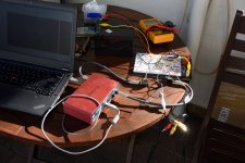
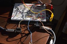
The set up photos are beginning! Thanks for this input, exactly what this thread needs.
Russellc
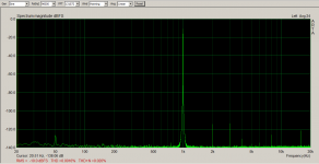
I've done a few adjustments and done some more measurements. These are using variations of the circuits posted above with resistor values that I had on hand in 0.1% Not quite as good as straight balanced loopback, but a whole lot better than an SE loopback!! When you see the pics of the setup it should be apparent that they can only get better with good layout
I'll post what is actually on the breadboard a bit later. Other values would probably be a bit better, but I just went with what I had on hand.
Note that the best results for this config seemed to be arta generator set at -10db and input pot configured to read -10db. Note I have not calibrated ARTA!
I also tried the switch in the inst position. The gain is MUCH higher. I had to turn down the generator to -25db and the noise floor rose to around -100db so inst setting is a no go.
Note also that mine is a first gen 2i2, the ones available for purchase now are 2nd gen, however I believe from testing that has been done here on diyAudio that 2nd gen also suffer the same degredation when running SE.
Tony.
Attachments
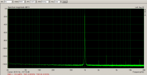
I did some more tests this afternoon. I found I had already made a new cable (and forgotten about it). Provided the earth connection is kept out of the picture for both output and input the loopback at least looks good. When lifting the output shield to the balanced to SE converter and taking the output of that to tip and ring of the input with no shield the results are on par (or in fact better) with those when passed through the SE to balanced comverter.
If the output shield is connected to common however then the results are no better than when using straight mono loopback cable.
Attached is the result with only the balanced to SE converter and the rca to TRS cable on the input.
I can try a test with just tip and ring for both output and input through an audio device and see how that goes. certainly loopback with just tip/ring and no sleeve gives comparible results to the bal to SE loopback posted in this post.
Tony.
Attachments
Last edited:
Silasmellor, note that the cables that I have used for doing SE measurements are using mono TS plugs, which means that the R and S are shorted, so one half of the differential pair is shorted out. The focusrite docco as far as I remember says that this is fine, and the standard way to connect to SE equipment however as shown the distortion performance suffers.
I'm guessing you may have used stereo plugs and left shield disconnected, only using the tip and ring?
Below is the thread for the gen2 measurements. http://www.diyaudio.com/forums/equi...2-2nd-gen-measurements-whats.html#post4927149
Tony.
I'm guessing you may have used stereo plugs and left shield disconnected, only using the tip and ring?
Below is the thread for the gen2 measurements. http://www.diyaudio.com/forums/equi...2-2nd-gen-measurements-whats.html#post4927149
Tony.
I have ordered some TRS to RCA converters to test with. I am quite sure that the Tip is connected to the center of the RCA and the Ring is connected to the Gnd of the RCA and the Sleeve is not connected but will check that when I receive them. Then I will use the Line settings of the 2i2. I hope it is possible to adjust both channels in the same time so they can be adjusted equal. It would also be nice to see an analog representation of the signals so e.g. the phase of the 2nd harmonic can be adjusted relative to the fundamental......like in 6l6s video.
Interested.
Would love to see detailed step by step instructions. This is an area I definitely need to be spoon fed.
Thanks Russellc!
nash
Same here, and that's exactly why I started the thread. This is about all I can personally contribute knowledge wise, this thread. I have 3 BA3 units, all of whose P3 sits in the middle position. The knob, heaven only knows what they are actually set to!
Hoping this develops to the point the the average joe, well at least one willing to read this, and buy the interface can adjust P3. Even not knowing exactly what one is doing shouldn't prevent the channels from at least being symmetrical. Once that is done, one can listen a while and then twiddle them one way and the other, maintaining the symmetrical adjustment and tune distortion to ones taste.....as I understand it, between 2nd and 3rd harmonic to one's preference. I may be way off here, I read about others saying they adjusting the 2nd harmonic in and out of phase.....this is all over my head. Sadly I am unable to even characterize what it is we are trying to measure. Any help from those more knowledgeable would be appreciated by all here I am sure.
Thanks to all contributors and readers needing this,
Russellc
Last edited:
- Home
- Amplifiers
- Pass Labs
- P3 Adjustment for the average Hobbyist