
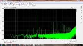
This looks a little better, I put a new battery in my meter.
ARTA Gen set to 0dB 20 bit.
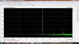
2i2 output level - rear sockets set to 1V rms to DRV134; input gain set to read 0dB on ARTA, dial glowing red; input gain backed off to -0.2dB, dial glowing green, 0.2dB makes a lot of difference. The other plots are the ARTA gen set to -3, -6 & -9dB.
ARTA Gen set to 0dB 20 bit.
2i2 output level - rear sockets set to 1V rms to DRV134; input gain set to read 0dB on ARTA, dial glowing red; input gain backed off to -0.2dB, dial glowing green, 0.2dB makes a lot of difference. The other plots are the ARTA gen set to -3, -6 & -9dB.
Attachments

You will see in the circuit that the the two halves (50r and 50r) of the 100r pot P3 are in parallel with R3 andR4 when P3 is in the middle position. If you measure across R3 and R4 they will each read 8.3r. Now if you turn P3 in a certain direction so that the leg in parallel to R3 is say 25r and the other leg parallel to R4 is 75r then R3 will read 7.14r and R4 will read 8.83r. As I turned P3 so that R3 was decreasing H2 started decreasing, then H2 reached its lowest value(most negative) and then as I turned P3 further in the same direction H2 started increasing while R3 decreased even further.
nash
nash
Yes! Thank you for this info. I remember 6L6 (IIRC) explainimg it wasn't just a matter of turning P3 a certain direction, it was like it shifted back and forth being turned in the same direction. Much appreciate your explanation!
BTW I have an almost finished Salas DCG3b going on right now....
Russellc
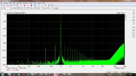
This looks a little better, I put a new battery in my meter.
ARTA Gen set to 0dB 20 bit.
2i2 output level - rear sockets set to 1V rms to DRV134; input gain set to read 0dB on ARTA, dial glowing red; input gain backed off to -0.2dB, dial glowing green, 0.2dB makes a lot of difference. The other plots are the ARTA gen set to -3, -6 & -9dB.
Iteresting. there is quite a drop from -3db to -6db. Looks like -6db might be the sweet spot.
edit: also try setting the averaging to linear or exp. It will hide the noise and leave the harmonics more visible.
Tony.
Last edited:
BTW I have an almost finished Salas DCG3b going on right now....
You must have a spare room to store all that sh*t😮
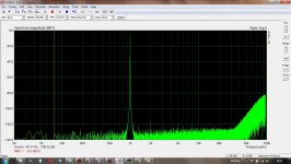
This looks a little better, I put a new battery in my meter.
ARTA Gen set to 0dB 20 bit.
2i2 output level - rear sockets set to 1V rms to DRV134; input gain set to read 0dB on ARTA, dial glowing red; input gain backed off to -0.2dB, dial glowing green, 0.2dB makes a lot of difference. The other plots are the ARTA gen set to -3, -6 & -9dB.
Why not turn on THD and THD+N thru the Setup dialog. I find with my albeit little experience that the setting where THD is the lowest is the best.
nash
You must have a spare room to store all that sh*t��
I have 4 systems that can run, 1 in one living room, 1 in another and 2 bedrooms, some extra components, and then theres the A7s in the basement with my only remaining tube amp. Could set up another bedroom, but its full of another hobby.
Russellc
Last edited:
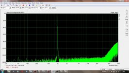
Also, try these settings in ARTA:
FS(HZ) = 96000
FFT = 16384
Wnd = Kaiser 5
Avg = Exp
Still not good.
Attachments
Last edited:
Still not good.
Looks pretty good to me! What are you trying to achieve?
You will see in the circuit that the the two halves (50r and 50r) of the 100r pot P3 are in parallel with R3 andR4 when P3 is in the middle position. If you measure across R3 and R4 they will each read 8.3r. Now if you turn P3 in a certain direction so that the leg in parallel to R3 is say 25r and the other leg parallel to R4 is 75r then R3 will read 7.14r and R4 will read 8.83r. As I turned P3 so that R3 was decreasing H2 started decreasing, then H2 reached its lowest value(most negative) and then as I turned P3 further in the same direction H2 started increasing while R3 decreased even further.
nash
nash
Just for absolute clarity, I understand your description of 100 ohm P3, being set to middle giving approximately 50r and 50r across legs parallel to R3 and R4. Then, measuring across R3 and R4 (ohms resistance I assume) yielded 8.3r cross each. (8.3r) OK, a little confused here, where am I measuring 50r? I get that across R3 or R4 you got 8.3r, (I assume ohms) or are you just saying that since its a 100 ohm pot set to the middle, each side has 50r of it, but if measuring R3 or R4 your result was 8.3r?
Then turning P3 in a certain direction, so that leg parallel to R3 is 25r and leg parallel to R4 is 75r (again not sure where this 25r and 75r are being measured) then R3 will measure 7.14r and R4 will measure 8.83r
Sorry to gunk up your clear description, but when I try to visualize all this I get confused on what is being measured where as to P3 being 50r 50r before P3 turned, and 25r 75r afterwards.
Sorry to be thick headed, and thanks for any additional clarity, I sure could use it!
Russellc
Last edited:
Hi Russellc,
With P3 set at midpoint, you can think of it as two "50 ohm" resistors in series.
Then R3 is now in parallel with the top "50 ohm", and R4 in parallel with the bottom
"50 ohm"
A 10 ohm resistor in parallel with a 50 ohm resistor gives you 8.33 ohms.
Cheers,
Dennis
With P3 set at midpoint, you can think of it as two "50 ohm" resistors in series.
Then R3 is now in parallel with the top "50 ohm", and R4 in parallel with the bottom
"50 ohm"
A 10 ohm resistor in parallel with a 50 ohm resistor gives you 8.33 ohms.
Cheers,
Dennis
And you can’t measure the resistance of either side of p3 in the circuit afaik, but you can calculate it from R3 or R4 as :
-1/P3(half a) = 1/R3 - 1/Rmeasured
Where R3 is the actual value of R3 and Rmeasured is the value measured across R3 in the circuit at a given P3 position.
Hope that makes sense.
-1/P3(half a) = 1/R3 - 1/Rmeasured
Where R3 is the actual value of R3 and Rmeasured is the value measured across R3 in the circuit at a given P3 position.
Hope that makes sense.
Last edited:
Hi Russellc,
With P3 set at midpoint, you can think of it as two "50 ohm" resistors in series.
Then R3 is now in parallel with the top "50 ohm", and R4 in parallel with the bottom
"50 ohm"
A 10 ohm resistor in parallel with a 50 ohm resistor gives you 8.33 ohms.
Cheers,
Dennis
Thanks!
Russellc
It's averaging -125dB noise floor, was hoping for better, harmonics are less than -120dB
there also seems to be some pick up - sproggies, there's one at 8Khz
Provided your BA3 is not better than that I think it should be fine. The 8Khz is a bit weird, but could be picking up from something nearby. Try turning off all flourecent lights and devices with switch mode power supplies (or take the whole thing outside and try measuring there). In reality your BA3 should not have anything you would be hoping to measure by the 8th harmonic anyway so it can be safely ignored.
You look to have well over 100db of headroom for your distortion measurements so unless the BA3 is less than say 0.0005% distortion I think you will be more than fine for doing the adjustment
")
Tony.
Last edited:
What was the IDSS?
I've been thing about that question. I bought a bunch of pairs from spencer years ago. None of the pairs was lower than 7.3 and none higher than 7.5. So what is in my BA-3 preamp is somewhere in that range.

So I've been experimenting with the adjustment of P3 this evening. I have another preamp besides the BA-3 FE. It's a DHT using a 45 tube which was built by Radu Tarta (another member here). I put the tube pre on the spectrum analyzer and it has a ton of second harmonic distortion. So my idea was to turn P3 to the point where it has the most in phase second harmonic distortion (P3 turned all the way CW where R3=1.7mV) to see if it sounded like the tube pre...it doesn't. But it did sound interesting (very laid back). Using this as a starting point I'm reducing the distortion, watching it on the spectrum analyzer, and using the voltage on R3 as a benchmark. Right now R3=10mV and some of the sparkle is coming back. It's a time consuming task (adjust P3, re-bias, listen, adjust P3, re-bias, listen...), but it's been fun.
- Home
- Amplifiers
- Pass Labs
- P3 Adjustment for the average Hobbyist