Hello
I was able to find a Novatel 400VA 18v 18v transformer
I could read somewhere on the forum that we can install a transformer from 300 VA to 500 VA 18V 18V
Should it then change some components?
I think of diode bridges or heatsinks or other...
Thank you
No need for component changes. The amp will only draw the current it needs, no matter the transformer size. Note that First Watt uses 300VA transformers which supply all the current the amp is designed for. Larger transformers won't hurt, but they don't add much beside weight and cost.
can I use 2SD669A in mountain view?
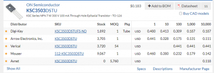
I don't know; I've never tried it myself. Doing a quick search on Octopart.com, I see that no American distributors sell the 2SD669A. Nobody here can buy one, including me.
A couple of places that specialize in obsolete, new-old-stock transistors seem to have 2SD669As to sell, for quite high prices. On the other hand, the NPN transistor called for in the Mountain View BOM and Mountain View schematic, is relatively cheap, and available from several sources; see Octopart.com results below.
Maybe you will bravely try the 2SD669A yourself, and report your findings here?
_
Attachments
M2x Experimental Daughterboards: Listeners wanted!
I've got a small number of new designs for an M2x daughterboard, and I'm asking for help with critical listening. These daughterboards measure reasonably well, but how do they sound? I have my own opinions, and I also seek the opinions of others.
Maybe, working together, we can discover which of these new daughterboards deserve a wide release. Most of them? A few of them? None of them? Depends on the general trend of the reviews. If the other reviewers and I happen to disagree with your opinion, please don't become viciously angry. It's just entertainment after all.
If interested & qualified, please shoot me a PM.
I've got a small number of new designs for an M2x daughterboard, and I'm asking for help with critical listening. These daughterboards measure reasonably well, but how do they sound? I have my own opinions, and I also seek the opinions of others.
If you've got a working M2x,
AND if you're willing to listen to one or more new daughterboard designs,
AND if you're willing to send me your notes and conclusions and remarks, MONTHS BEFORE you publicly release them to other people,
AND if you've already built, listened to, and publicly reviewed AT LEAST THREE of the five daughter cards (I, MV, N, A, T) which ship with M2x,
THEN I'd like to send you a sequence of daughterboards for audition. Take as much time as you need (but of course I prefer sooner!), and keep each pair of daughterboards with my compliments, when you finish the review. Or throw them away if you despise their sound. When you hand in your review of CandidateX I'll send you Candidate(X+1) etc.
Maybe, working together, we can discover which of these new daughterboards deserve a wide release. Most of them? A few of them? None of them? Depends on the general trend of the reviews. If the other reviewers and I happen to disagree with your opinion, please don't become viciously angry. It's just entertainment after all.
If interested & qualified, please shoot me a PM.
All
The M2X cards, lsj170 and lsj74 too, have been ordered since yesterday.
The project will continue...purchase components...4 weeks waiting for the edcoor... welding etc...
And at the end it is necessary to switch on and adjust the amplifier.
what is the Bias or Offset setting procedure
I can't find these elements in the forum.
Does the adjustment have to be done again each time the card is changed?
Can you help me?
Thanks
M2X OFFSET ADJUSTMENT PROCEDURE
M2 (and M2x) includes Nelson Pass's very nifty "Optical Bias" circuit which sets and continuously monitors bias current in the output stage. This means there is no bias adjustment in the M2 or M2x; the circuit powers up and adjusts itself to the desired bias current, with no trimming needed. NP filed for a patent on this idea in 1987 and the patent was issued in 1988: link to .pdf
There is however an OFFSET adjustment. It is potentiometer "RV1" on the M2x schematic. The offset adjustment is potentimeter "P1" in The Official M2 Schematic posted by Nelson Pass himself, on 24 October 2015. Please study the two schematics side by side, you'll find they are extremely similar, including identical component designators ("R2" , "Q5" , etc) and identical component values.
Now read M2x post #3, especially list item 3. There is one place where you might want to commit blasphemy and deviate from Nelson Pass's Official M2 Schematic. Read about it, think about it, and make your decision.
You should adjust the offset of each channel before you ever connect a loudspeaker; otherwise you might accidentally send DC through your voice coil(s) and melt your speakers.
Insert shorting plugs into the input RCA jacks. You want the amplifier inputs shorted to ground during offset adjustment.
Connect a dummy load resistor rated for at least 25 watts; you can find some at very low prices on eBay link. If you worry that eBay sellers are optimistic liars, if you worry that a "100 watt" eBay resistor will melt when you pump 20 real world watts through it: buy a different ohms value and put two of them in series. (or put two of them in parallel). Now you've got a 200 "eBay watts" resistor which might handle 20 real world watts without difficulty.
Place your load resistor on a heatproof surface -- the resistor might get very HOT! Turn on the M2x and connect your DVM to measure the DC voltage across the loudspeaker posts. Dial the potentiometer RV1 until the DC voltage across the loudspeaker posts is zero.
Then wait for an hour to let the amplifier and heatsinks warm up.
Now look at the DC voltage across the loudspeaker posts, and dial potentiometer RV1 until the voltage across the loudspeaker posts is zero.
Then wait for one more hour to let everything warm up some more. Dial RV1 again to get zero offset at the loudspeaker posts. And now you're done. Play music.
Of course this is YOUR amplifier and you can do anything to it that makes you happy. If you wish, you can play music for a few weeks and give the amplifier time to "settle down" and/or "break in". Then do it all again. Disconnect the speakers and perform the entire offset adjustment procedure one more time. Nobody thinks this is necessary, but it does feel very satisfying to people with Obsessive Compulsive Disorder.
Last edited:
Now read M2x post #3, especially list item 3. There is one place where you might want to commit blasphemy and deviate from Nelson Pass's Official M2 Schematic. Read about it, think about it, and make your decision.
I strongly suggest including this change that Mark has accommodated in the M2x. There's absolutely no downside to it, and it helps ensure proper operation and adjustment for the majority of builders.

Last edited:
Pass DIY Addict
Joined 2000
Paid Member
Connect a dummy load resistor rated for at least 25 watts
Ha- I can almost here ZM now: "Those are sissy power resistors..."
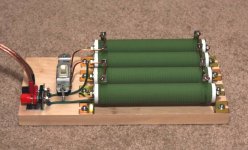
Check out MPJA for a nice assortment of power resistors.
Two of these in parallel are good for 8R at 240w and four in parallel provides an 4R load rated for 480w. Install a regular wall switch in the middle and now you can change resistance load with ease!
Attachments
Last edited:
Pass DIY Addict
Joined 2000
Paid Member
I'm usually putting my amps under the rug , so no biggie where load is

Underfloor heating?
Pass DIY Addict
Joined 2000
Paid Member
.
Connect a dummy load resistor rated for at least 25 watts
Hi Mark, is this a specific procedure to set the offset on the M2(x)? I don’t believe (I could be wrong) that it’s mentioned in the other build guides, or atleast not in the Aleph J guide. When I tested my J, I measured offset without a resistor across the speaker posts and all seems ok with my amp.
M2 (and M2x) includes Nelson Pass's very nifty "Optical Bias" circuit which sets and continuously monitors bias current in the output stage. This means there is no bias adjustment in the M2 or M2x; the circuit powers up and adjusts itself to the desired bias current, with no trimming needed.
could I just add that this is the coolest thing ever !
even though I knew the pot was there for offset adjustment, I had to fight the greatest urge to tweak the bias as it gently started to rise and then settle at the predetermined bias.
and while we are disclosing things - beware !! it is possible to blow a mosfet by setting the offset to far to one side with the modifications noted.
Not being OCD and a little cavalier I was trying to adjust offset of one board while measuring the other board
 and couldn't understand why I wasn't seeing any change and decided to set it at one extreme and then move towards the other ---- mosfet did not like this move and very quickly released the sacred dust. Luckily I had a spare (I am using Toshibas) and restored the amp to normal function easily.
 After that initial burn in and settling, I have not seen the offset drift at all - I am OCD in this sense that I do not fully trust things until there is sufficient evidence to prove it will not destroy my main speakers.
..dB
Back in post 432, Mark posted a fill-in the blank schematic for the Moffet Field. I've built a 24 mA version (pic below) but I'm shooting for 30 mA with another set of JFETs (J112). The zener D2 has been replaced with a ZTX450 npn, which I might or might not keep. I chose it mostly because it was small and had ebc pinout. I'll post a schematic and some data later after I'm sure it won't self-destruct.
Phil
Phil
Attachments

- Home
- Amplifiers
- Pass Labs
- The diyAudio First Watt M2x