Beautiful build! Congratulations. Glad to see the green sleeve Nichicon UES capacitors on the main amp board and also on the daughter card.
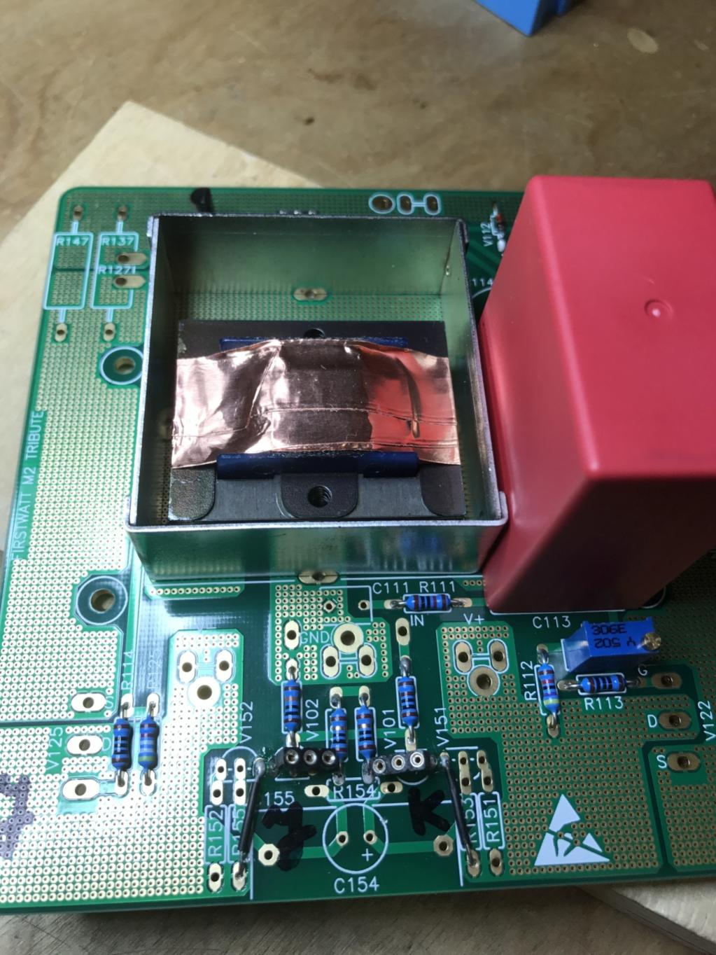
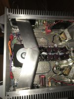
Under the speaker binding posts we can barely see the third CL60 ICL device, connected to chassis ground. What insulates the other leg of that CL60, preventing it from shorting to the perforated metal floor of the chassis?
_
Under the speaker binding posts we can barely see the third CL60 ICL device, connected to chassis ground. What insulates the other leg of that CL60, preventing it from shorting to the perforated metal floor of the chassis?
_
Attachments
I hope so too!
The Texas A&M repair, which requires no de-soldering and re-soldering, is simply to affix a piece of black electrician's tape to the chassis floor, underneath that lead. Or for extra bonus points, use a color inkjet printer to print the FirstWatt logo onto an Avery label (example), and affix that sticker to the floor, beneath the wire lead. It's an insulator disguised as a promotion!
The Texas A&M repair, which requires no de-soldering and re-soldering, is simply to affix a piece of black electrician's tape to the chassis floor, underneath that lead. Or for extra bonus points, use a color inkjet printer to print the FirstWatt logo onto an Avery label (example), and affix that sticker to the floor, beneath the wire lead. It's an insulator disguised as a promotion!
Or for extra bonus points, use a color inkjet printer to print the FirstWatt logo onto an Avery label (example), and affix that sticker to the floor, beneath the wire lead.
LOL!
Beautiful build! Congratulations. Glad to see the green sleeve Nichicon UES capacitors on the main amp board and also on the daughter card.
Under the speaker binding posts we can barely see the third CL60 ICL device, connected to chassis ground. What insulates the other leg of that CL60, preventing it from shorting to the perforated metal floor of the chassis?
_
The PSU side of the CL60 is covered in heat shrink tubing and elevated 1/4" above the chassis. Of course the other side is bare but tied to the chassis ground via a ground lug. This is similar to 6L6's builds.
Attachments
Last edited:
Beautiful! Thanks for the details. I misinterpreted 2 pixels of "shiny" in the photo and jumped to the conclusion that the wire might possibly be uninsulated. Please accept my apologies.The PSU side of the CL60 is covered in heat shrink tubing and elevated 1/4" above the chassis. Of course the other side is bare but tied to the chassis ground via a ground lug. This is similar to 6L6's builds.
BTW your IPS bolts are a well-chosen length, congratulations. Nelson Pass gently mocked 6L6 and me for installing quite long bolts (20mm!) in the first M2x build. See posts #13 and #17 in this thread. Most of the sting has dissipated, with the passage of time.
BTW your IPS bolts are a well-chosen length, congratulations. Nelson Pass gently mocked 6L6 and me for installing quite long bolts (20mm!) in the first M2x build. See posts #13 and #17 in this thread. Most of the sting has dissipated, with the passage of time.
The longer bolts provide a greater margin of safety for being able to place the lockwashers and keep them from falling off before getting the nuts to catch. Fat fingers and tiny spaces!
BTW your IPS bolts are a well-chosen length, congratulations. Nelson Pass gently mocked 6L6 and me for installing quite long bolts (20mm!) in the first M2x build. See posts #13 and #17 in this thread. Most of the sting has dissipated, with the passage of time.[/QUOTE]
I’ve heard that it’s not the size of the bolt that matters, but how you use it 😉Lol. I’ll also probably end up using the longer bolts, I’m 95% done with my parts purchases 🙌🏻. Can’t wait to get soldering!
I’ve heard that it’s not the size of the bolt that matters, but how you use it 😉Lol. I’ll also probably end up using the longer bolts, I’m 95% done with my parts purchases 🙌🏻. Can’t wait to get soldering!
Phil, if you decide to cook up your own Zobel network to match your own Edcor transformer, I'm sure a lot of readers here would love to see a frequency response plot of your Edcor (a) using the Official M2 Schematic design and parts values of the Zobel; and also (b) using your final choice of Zobel network, that you settled upon after experimenting with the Edcor on your Analog Discovery 2, using your new optimized parts values.
You bet Mark. I built a test board using a stripped down OPA604 Tucson board powered directly from a +/- 15VDC supply and some parts (C2, C3, R7, R6, RV1) on the main board. I put test points at the ends of the R5C1 Zobel to be able to test some variations. My first measurements will be over the batch of 6 Edcors, with and without Zobel, to see what extent - if any - matching is important. Getting the data is easy but it's been too long since I've used a spreadsheet for graphing
 but hope to have some plots in a few days.
Phil
Attachments
I just ordered parts for a M2X build and have a question
I just took the plunge into DIY audio territory by ordering the PCB boards to build an M2X. I was torn between this design and the Aleph J (I have the boards on hand for it too), but liked the fact it had a higher power level into 4 ohms, and that I could try different input stages.
I will build it with the standard Ishikawa input stage, as this was how Nelson Pass did it, and I want to spend a fair bit of time listening to how it sounds so I have a baseline for comparison. I ordered the necessary transistors for the main amplifier boards and the Ishikawa input stage yesterday.
I am on a pretty limited budget, and can't afford to buy everything at once, so it will take me a few months to get all the parts together. I expect to have everything before Christmas, and my goal is to have the amplifier finished sometime in January.
In the meantime, I will keep reading what others are doing with this (and the other First Watt) power amplifier.
I am sure I will have a few questions along the way. In fact, here is my first question:
"What tools do most people deem essential for building electronic projects like this one?"
Where can one get the cover for edcor trafo?
It's a TEKO 3710.
I got mine at Reichelt, Germany:
at reichelt elektronik
Best regards,
Claas
Thanks Claas.
I have noticed that if i put my hand around it, the buzz on output goes down. So shealding is probably good idea.
Right now it has about 0.4mV on average on the output, 1.5mV peak to peak, with my small handheld oscilloscope, not too precise.
What do people normally measure on the output? Otherwise it sounds great.
I actually had just checked residual hum / AC on the outputs of my M2 a few days ago and measured between 0.1 - 0.2 mV with my DMMs.
I have built my M2 on JPS boards, with the Edcors centrally mounted.
The following hum-reducing measures have been used:
- grounded TEKO shields over the Edcors
- oh, and I put a copper belly band around the Edcors as well ...
- mains transfomer (Toroidy 20V / 500 VA with grounded shield) rotated for minimum hum
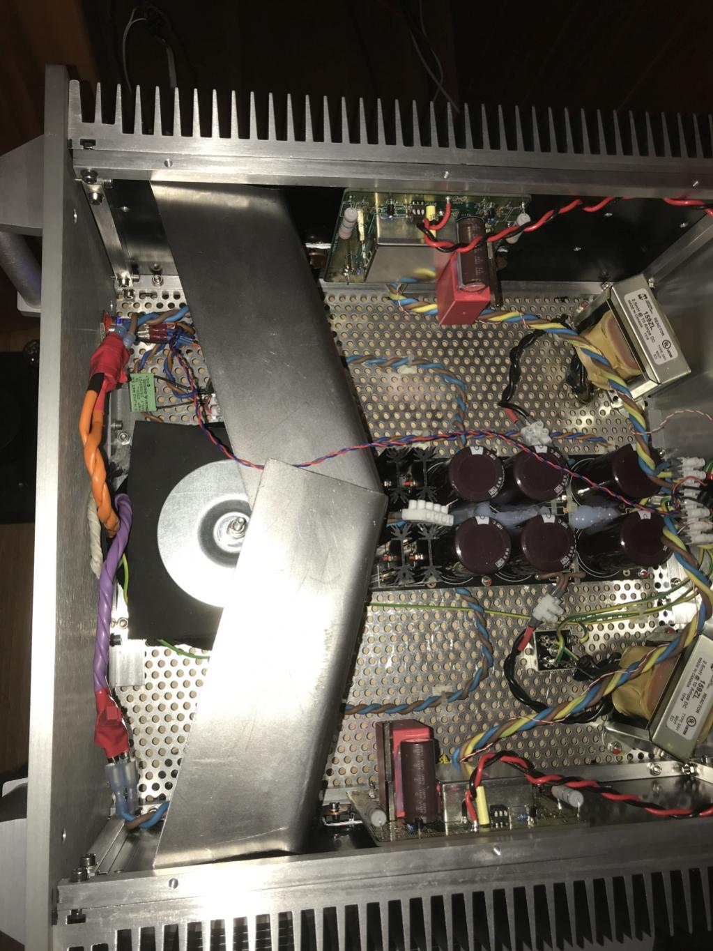
- shield between transfomer and rectifier bridges on one side, PSU and amp boards on the other side (see attached photo). Shield is made from magnetic steel.
On the other hand, I have a CLC PSU with the chokes mounted at the rear of the chassis. That may give a bit of additional hum, though holding a steel sheet between chokes and amp board, I didn't hear a significant difference.
With 0.4 mV you would be within FirstWatt's noise spec of 500 µV.
However, I have 100 dB/W sensitive widebanders, and with my 0.1 - 0.2 mV residual hum I'm still hearing a faint hum with my ear directly at the Fostex widebander. It's practically silent with the ears at 30 cm from the driver, even in a very quiet room - good enough
My Aleph J was absolutely silent with the same PSU and my ear at the speaker driver; but on the other hand had turn-on / turn-off thumps ...
Best regards,
Claas
I have built my M2 on JPS boards, with the Edcors centrally mounted.
The following hum-reducing measures have been used:
- grounded TEKO shields over the Edcors
- oh, and I put a copper belly band around the Edcors as well ...
- mains transfomer (Toroidy 20V / 500 VA with grounded shield) rotated for minimum hum
- shield between transfomer and rectifier bridges on one side, PSU and amp boards on the other side (see attached photo). Shield is made from magnetic steel.
On the other hand, I have a CLC PSU with the chokes mounted at the rear of the chassis. That may give a bit of additional hum, though holding a steel sheet between chokes and amp board, I didn't hear a significant difference.
With 0.4 mV you would be within FirstWatt's noise spec of 500 µV.
However, I have 100 dB/W sensitive widebanders, and with my 0.1 - 0.2 mV residual hum I'm still hearing a faint hum with my ear directly at the Fostex widebander. It's practically silent with the ears at 30 cm from the driver, even in a very quiet room - good enough
My Aleph J was absolutely silent with the same PSU and my ear at the speaker driver; but on the other hand had turn-on / turn-off thumps ...
Best regards,
Claas
Attachments

I am sure I will have a few questions along the way. In fact, here is my first question:
"What tools do most people deem essential for building electronic projects like this one?"
There's a list of tools with links in the ACA build guide. It's just above the first step. It's not 100% complete, but pretty darn good, and I'm sure you have some of the various tools already, so take a look and see if there's any obvious omissions, or of some things look like they'd be very useful.
Amp Camp Amp V1.6 Build Guide - diyAudio Guides
- Home
- Amplifiers
- Pass Labs
- The diyAudio First Watt M2x