Don't you think that the variance in drive impedance might reflect enough to make the exact values different for each input stage? I don't know how much the transformers can vary.
I talked to Nelson Pass about the transformers once. He said that First Watt assigned a summer intern to measure the frequency response of every incoming Edcor transformer, so they could eliminate the outliers and only ship the good ones.
Whether IPS_Zout interacts with the Zobel, producing a perceptible change in the sound of the amplifier, I have no idea. It certainly does vary by a factor of at least 500-to-1 across the five M2x daughter cards. Thanks to the presence or absence of integrated circuits and their enormous Avol at DC. It'd be fun to mock up a modified Tucson board which adds a 1 watt 100 ohm trimpot (and bypass jumper) in series with the output. What Zout sounds best to your ears, Mr. Wurcer?
I started these questions because there are no part numbers for the non-3W resistors. Did I miss them or delete them somehow????..Also - if you look at the part's listing on Mouser (enter the part number in the BOM and look at the page) all the data necessary to choose an equivalent will be there, as it will list value, tolerance, voltage rating, lead spacing and size, etc...
Sorry if that was the case.
Best regards,
Rafa.
What Zout sounds best to your ears, Mr. Wurcer?
I'll find out eventually, packing now for hopefully the last move. Any classic through hole parts you might need, rms converters, in-amps, multipliers, etc. No fakes, I guarantee (sorry I gave my last AD1862/65's away a couple of years ago).
Start with R13-R14. They are 0R47 3W 5% metal oxide resistors and a specific part number is given in the BOM. You need four pieces of this resistor to build a stereo pair of M2(x) amp....For those who might wish to boast that their M2 amplifier, lovingly hand-built in their own home workshop, is so much better....
Vishay | Mills source resistors is new product in stock at Mouser.
Not very cheap 4 pcs.= 10$
https://eu.mouser.com/ProductDetail...=sGAEpiMZZMtbXrIkmrvidNRNJp1YrdA3CgRAAiLyIXI=
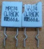
another type is MPC74 made by Futaba Company in Japan cost 5 pcs.= 5 $
RS have this in stock from time to time.
MPC74 0R47 J | Fukushima Futaba MPC Series Solder Metal Plate Resistor 470mΩ +-5% 5W +-350ppm/degC | RS Components
https://docs-emea.rs-online.com/webdocs/156d/0900766b8156d150.pdf
Smooth music with superb clear and deep jumping bass.
Try by Yourself don't believe me

Attachments
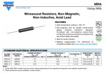
It is interesting to note that the 3W resistor proposed in the BOM, while of higher tolerance (5%) has a flat derating curve up to 70ºC (which is the temperature mine are working at in the ACA amp).Vishay | Mills source resistors is new product in stock at Mouser.
Not very cheap 4 pcs.= 10$
MRA-05R4700FE12 Vishay / Mills | Mouser Europe...
The ones by Vishay, while narrower tolerance (1%), start loosing power at 25ºC, and by 75ºC have around 80% of the rated power. Would that affect some characteristics of the amp?
Best regards,
Rafa.
I'd love a quad of 797s in thru hole, white ceramic + gold lid even better. For that neener neener unobtainium cred on the DIY gear display tables at Burning Amp in 2019.
Say no more, we never put 797's in the white ceramic (those packages were very gold intensive) but I can find a few other candidates. I think I have some cerdip 797's though.
Member 6L6 measured the AC power consumption of his M2x. You could use his measurement to estimate the power dissipated in R13 and R14.
Assume DC power = AC power measured by 6L6; i.e. no power dissipated in the CL60 inrush current limiters and no losses in the toroidal power transformer. Assume the input stage and the optoisolator stage (bias stack) consume negligibly small amounts of power.
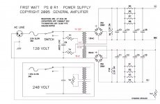
The 2 x 18VAC transformer + First Watt power supply design, produces plus and minus 23 volts DC.
Then DC power = 2 x (23 volts) x (DC current) = AC power measured by 6L6
Then DC current = (1/46) x (AC power measured by 6L6)
Half of the current flows in the Right Channel amplifier board, and the other half flows in the Left Channel amp board
Then current in Right Channel R13 = (1/2) * (1/46) * (AC power measured by 6L6)
Then power dissipated in Right Channel R13 = 0.47 ohms * DCcurrent * DCcurrent
and boom you're done. Compare calculated power in R13, versus its power rating and versus its datasheet.
Since M2x is a Class A amplifier, max power dissipation occurs at idle, with no input signal. It's a DC calculation.
Just find out what AC power consumption member 6L6 measured on his M2x, and tap a few keys on a calculator. It's not rocket surgery.
You could also look it up in the First Watt M2 manual. It's right there on page 10 of the pdf file.
Assume DC power = AC power measured by 6L6; i.e. no power dissipated in the CL60 inrush current limiters and no losses in the toroidal power transformer. Assume the input stage and the optoisolator stage (bias stack) consume negligibly small amounts of power.
The 2 x 18VAC transformer + First Watt power supply design, produces plus and minus 23 volts DC.
Then DC power = 2 x (23 volts) x (DC current) = AC power measured by 6L6
Then DC current = (1/46) x (AC power measured by 6L6)
Half of the current flows in the Right Channel amplifier board, and the other half flows in the Left Channel amp board
Then current in Right Channel R13 = (1/2) * (1/46) * (AC power measured by 6L6)
Then power dissipated in Right Channel R13 = 0.47 ohms * DCcurrent * DCcurrent
and boom you're done. Compare calculated power in R13, versus its power rating and versus its datasheet.
Since M2x is a Class A amplifier, max power dissipation occurs at idle, with no input signal. It's a DC calculation.
Just find out what AC power consumption member 6L6 measured on his M2x, and tap a few keys on a calculator. It's not rocket surgery.
You could also look it up in the First Watt M2 manual. It's right there on page 10 of the pdf file.
I'd love a quad of 797s in thru hole, white ceramic + gold lid even better. For that neener neener unobtainium cred on the DIY gear display tables at Burning Amp in 2019.
Ahahah, these old types....
Attachments
It is interesting to note that the 3W resistor proposed in the BOM, while of higher tolerance (5%) has a flat derating curve up to 70ºC
(which is the temperature mine are working at in the ACA amp).
The ones by Vishay, while narrower tolerance (1%), start loosing power at 25ºC, and by 75ºC have around 80% of the rated power.
Would that affect some characteristics of the amp?
Best regards,
Rafa.
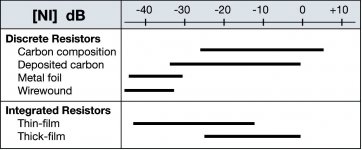
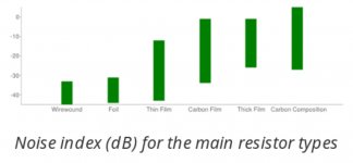
Low temperature coefficient ppm is always better , all resistors types are different :
materials, mechanical construction for example metal film compare to metalband etc.
0R47 Panasonic 3watt's are very good too but for make low resistances values = less 1 Ohm match ,
we need multimeter with 4 wires Kelvin mesurements option.
Yes resistors affect little charecteristics of the amp ( let's try build one M2 with carbon composite haha ) , capacitors much more and input transformer and transistors influence ( sweet spot ) to the final sound are huge
") Best regards
Best regardsI'll find out eventually, packing now for hopefully the last move. Any classic through hole parts you might need, rms converters, in-amps, multipliers, etc. No fakes, I guarantee (sorry I gave my last AD1862/65's away a couple of years ago).
Good luck with the move, Scott. I wish I was close enough to pack up a box of your stuff and add it to my stuff in the basement. My daughters are going to be cursing when I make the real big last move.
Sorry if I'm just obtuse, but I can't find info on the voltages required from the PSU. What specs are required?
Thanks,
Rafa.
PSU schematic for M2xAttachments
Depending upon how much empty space you have inside your chassis, one or the other of these two Antek transformers would be an excellent choice:
Click on the three little thumbnail images at the left side of the web page, to see photos and datasheets.
Click on the three little thumbnail images at the left side of the web page, to see photos and datasheets.
Thanks for the answers!! So, if I were to plan in advance to buy parts to build an M2x when the PCBs are available and have the case also compatible with, say, a future F6... is there any chance to make the PSU more or less 'universal'? One requires +-25V while the other is listed for +-23V ... (although the schematic for the F6 PSU is identical to the one posted by Soundhappy, so not sure what makes those +-2V difference?).
Maybe I'm just over complicating things and there is no need for both and their similarities would make building both a bit redundant... I just wanted to know if there is a way to make it a truly 'universal' PSU for the different FirstWatt amps or if there are enough differences that require each to have a different PSU.
Thanks.
Rafa.
ps. Perhaps this was better asked in the PSU thread? Still, since the M2x is the on I will most likely build first, I jumped here first.
From 6L6's F6 build guide:
Go for it and have some fun!
diyAudio Mosfet F6
Power Supply
The F6 uses the same type of PSU as found in essentially all the other Firstwatt amplifiers (F5, F4, Aleph J, etc…) - +/-25Vdc rails, approx. 60,000uF filtering per rail. The diyAudio universal PSU board will work well for this.
Transformer 300-400VA 18+18Vac secondaries, shielded if available. Antek AS-3218 or equivalent (Bigger is useable if you have it, but 300-400VA is about perfect.)
Filter resistors (8) 0.47ohm 3W
Filter Capacitors (8) 15,000uF 25V minimum 10mm Snap-In 35mm max diameter (Bigger caps don’t hurt, but watch your inrush, you may need a bigger fuse.)
Go for it and have some fun!
Rafa- Yes, a PSU for the M2x could also power an Aleph J. (hint hint hint) All you would have to do is change the amplifier boards.
And F4, F5, F6....but A-J would be a pretty good place to start.
- Home
- Amplifiers
- Pass Labs
- The diyAudio First Watt M2x