New member, so please bear over with me.
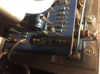
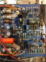
See below photos - any ideas as to what has happened and if it is an easy fix/replacement?
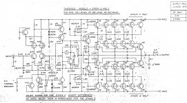
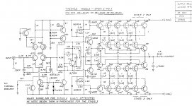
Schematics for Stasis 3 would be helpful too.
See below photos - any ideas as to what has happened and if it is an easy fix/replacement?
Schematics for Stasis 3 would be helpful too.
Attachments
Last edited:
Some more knowledgable forum members will chime in and most probably be able to provide schematics as well.
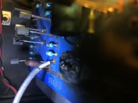
In the meantime I would suggest to take better pictures as you will be asked for anyway.
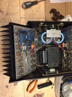
You will have to get better acces to that channel PCB as well if you want to troubleshoot that amp.
In the meantime I would suggest to take better pictures as you will be asked for anyway.
You will have to get better acces to that channel PCB as well if you want to troubleshoot that amp.
")
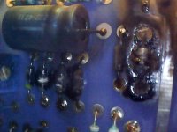
Both times my old Nad 3150 has failed (smoked) was caused by shorted caps (electrolytic). When this happens it can destroy some transistors and resistors. Now most caps has been replaced......it is a 35 - 40 year old amp now.....most electorlytic caps does not like to be more than 40 years old.......
OT: Presumably those Threshold schematics were hand drawn. They are absolutely beautiful.
Pre-computer age. George Cusick was our in-house draftsman.
Repair
Guy by name of Jon Soderberg can repair or update components for old stasis units. I think you could just Google him to check it out. He used to work for Threshold from what I understand. My Threshold Stasis 2 was bought new 38 years ago and has been in continuous use in my main system and still making me happy. If can get it up and running you will be happy. I built a Pass designed BA3 based system for my small room system and like that too
Guy by name of Jon Soderberg can repair or update components for old stasis units. I think you could just Google him to check it out. He used to work for Threshold from what I understand. My Threshold Stasis 2 was bought new 38 years ago and has been in continuous use in my main system and still making me happy. If can get it up and running you will be happy. I built a Pass designed BA3 based system for my small room system and like that too
Finally I got a picture of the board. Could anyone based on these photos give any ideas as to the failure and suggestion for next steps. Many thanks in advance.
Attachments


-proper photoshoot session , to ensure easier assembly later
-check all outputs in situ with diode test ; if there is short somewhere , you need to disassemble complete group , to locate Dodo transistor (if that's the case , we are going to deal later)
-check one by one all resistors on output pcbs
-desolder all wires from pcb ;
-remove all burned resistors , clean pcb with alcohol, replace resistors
-check all resistors
-replace all electrolyts on both pcbs
-replace all Tantalum caps , either with electrolyts or solid caps
- desolder one by one all semiconductors on pcb , check , replace if Dodo
solder wires again , mount back , prepare Bulb tester
Last edited:
- Status
- This old topic is closed. If you want to reopen this topic, contact a moderator using the "Report Post" button.
- Home
- Amplifiers
- Pass Labs
- Stasis 3 - one channel burned