I've been simulating the signal currents that flow in the primary of the First Watt M2's input transformer. And this has led me to a discovery: I might be badly mistaken, but I think the circuit is discussed erroneously in the user manual. Here is the pencil and paper explanation.
The relevant piece of the M2 schematic is attached below as figure 1.
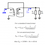
I think the user manual describes this, in the passage which is attached below as figure 2. Please have a look at the red underline. I think this is saying that the impedance looking into the primary of the transformer, is 6K ohms. That's what I drew on figure 1 above.
To analyze the impedance we treat C2 and C3 as short circuits, and we treat V+ and V- as AC-grounds. Then the transformer secondary is loaded by R6 and R7 in parallel, plus another big nasty mess caused by the Cgd's of the output MOSFETs, which I will assume is super high impedance and thus negligible.
What I get is displayed in figure 3 below. The Edcor transformer has a turns ratio of 5-to-1. {Math check: 600 = 15K / (5*5)}. So the impedance on the secondary, 23.5K, is reflected back to the primary, by a factor of 6 squared. Thus Zin = 23500/36 = 653 ohms.
But the manual says 6000 ohms. Where have I gone wrong?
If anyone happens to be wondering, "Does simulation agree with the pencil and paper explanation?" the answer is yes.
The relevant piece of the M2 schematic is attached below as figure 1.
I think the user manual describes this, in the passage which is attached below as figure 2. Please have a look at the red underline. I think this is saying that the impedance looking into the primary of the transformer, is 6K ohms. That's what I drew on figure 1 above.
To analyze the impedance we treat C2 and C3 as short circuits, and we treat V+ and V- as AC-grounds. Then the transformer secondary is loaded by R6 and R7 in parallel, plus another big nasty mess caused by the Cgd's of the output MOSFETs, which I will assume is super high impedance and thus negligible.
What I get is displayed in figure 3 below. The Edcor transformer has a turns ratio of 5-to-1. {Math check: 600 = 15K / (5*5)}. So the impedance on the secondary, 23.5K, is reflected back to the primary, by a factor of 6 squared. Thus Zin = 23500/36 = 653 ohms.
But the manual says 6000 ohms. Where have I gone wrong?
If anyone happens to be wondering, "Does simulation agree with the pencil and paper explanation?" the answer is yes.
Attachments
I've been simulating the signal currents that flow in the primary of the First Watt M2's input transformer. And this has led me to a discovery: I might be badly mistaken, but I think the circuit is discussed erroneously in the user manual. Here is the pencil and paper explanation.
The relevant piece of the M2 schematic is attached below as figure 1.
I think the user manual describes this, in the passage which is attached below as figure 2. Please have a look at the red underline. I think this is saying that the impedance looking into the primary of the transformer, is 6K ohms. That's what I drew on figure 1 above.
To analyze the impedance we treat C2 and C3 as short circuits, and we treat V+ and V- as AC-grounds. Then the transformer secondary is loaded by R6 and R7 in parallel, plus another big nasty mess caused by the Cgd's of the output MOSFETs, which I will assume is super high impedance and thus negligible.
What I get is displayed in figure 3 below. The Edcor transformer has a turns ratio of 5-to-1. {Math check: 600 = 15K / (5*5)}. So the impedance on the secondary, 23.5K, is reflected back to the primary, by a factor of 6 squared. Thus Zin = 23500/36 = 653 ohms.
But the manual says 6000 ohms. Where have I gone wrong?
If anyone happens to be wondering, "Does simulation agree with the pencil and paper explanation?" the answer is yes.
In the first paragraph Nelson mentions "input impedance of output stages".In the 3rd paragraph he mentions "input impedance of this system" which I think are the same meaning. 1/47k+1/47k+1/10k=1/Zin=about 7K ohms.I think you are mixing up input impedance looking into the primary of the autoformer vs. input impedance of the output stages.
1/47k+1/47k+1/10k=1/Zin=about 7K ohms.I think you are mixing up input impedance looking into the primary of the autoformer vs. input impedance of the output stages.
If you're talking about R5=10K, that's part of a Zobel network that shapes the HF response of the transformer. Notice that the R5+C1 Zobel only begins to have an effect at 23.4 kHz and higher.
However: IF the transformer DOES happen to drive 7K, then the impedance looking into its primary is 7000/36 = 194 ohms. That's a mighty heavy load for a couple of dinky little TO-92 source followers to drive, especially when you notice that the amplifier's I/O spec says "3VRMS input needed to deliver full rated power to the load". 3V/194ohms = 15 mA RMS output of the source followers (21 mA peak) ... more than their Idss! You'd need to forward-bias the gate/source junction to get that much current. Ugh.
Last edited:
xformer see OS as ~23K
xformer voltage transfer ratio is 6x
xformer impedance ratio is 6^2=36
so , buffer see 23k/36~640
all that using ideal values , not actual measurements , but that will give 10% diff. max
10K-680p is irrelevant at audio freq.
Papa is often making practical jokes , knowing that half of bunch is not reading at all , half is reading but knows station , half is reading and spotting illogical point but is scarred to ask
Papa is often making practical jokes , knowing that half of bunch is not reading at all , half is reading but knows station , half is reading and spotting illogical point but is scarred to ask
Too many halves
")
So that's two people who think the circuit is discussed erroneously in the user manual.
Personally, I doubt the error is intentional; why tell a deliberate lie in a document that you send along with an amplifier you just sold for $3000 ? It may alienate an otherwise loyal customer. Hanlon's Razor suggests that "accidental mistake" is the preferred explanation, rather than "intentional falsehood". Wikipedia discusses further.
Personally, I doubt the error is intentional; why tell a deliberate lie in a document that you send along with an amplifier you just sold for $3000 ? It may alienate an otherwise loyal customer. Hanlon's Razor suggests that "accidental mistake" is the preferred explanation, rather than "intentional falsehood". Wikipedia discusses further.
When Papa is in case , intentional misleading is out of question ....... even not considering fact that there can be no any benefit from mislead .
And even not counting on fact that 90% of same industry is consciously lying most of the time ........ I really must stop here , or ......
Count only on fact that he's always in inventing mood , while writing manual is certainly lesser satisfying job .
And even not counting on fact that 90% of same industry is consciously lying most of the time ........ I really must stop here , or ......
Count only on fact that he's always in inventing mood , while writing manual is certainly lesser satisfying job .
I get notional 652.777 Ohms. As you say.
And he works the 600:15K windings pretty much spot-on the design spec.
The diff 6K versus 653 will not bother most users. Still, it "can't be right", and smacks of a lost decimal place.
But there are two 47K resistors hanging on that point. Mark's math just assumed the 23.5K and neglects Gates and Zobel (which are first-order neglectable).
And he works the 600:15K windings pretty much spot-on the design spec.
The diff 6K versus 653 will not bother most users. Still, it "can't be right", and smacks of a lost decimal place.
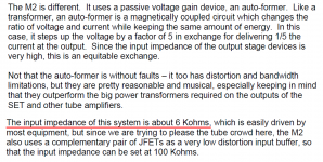
...The input impedance of those source followers is very high.
But there are two 47K resistors hanging on that point. Mark's math just assumed the 23.5K and neglects Gates and Zobel (which are first-order neglectable).
......
In any case, I think we've arrived.
let's use this thread for something really useful:
Mr. MR - is there a posibility to add Atom subscription thingie to your blog ?

Reread the User Manual excerpt in post #1, and see if you agree that the dual JFET front end is only needed when driven by a tube preamp. All other preamps could easily (?) drive the 653 ohm input impedance of an M2-without-JFETs, wouldn't you say?
No, I wouldn't say a 600 ohm input impedance is an easy load for all non-tube preamps, that's why I thought he may have been referring to the generic example in the manual, since that is the context.
We can just ask the man himself though, and save ourselves the tedium.
One of my current projects is a no-Toshiba-JFETs reimplementation of the M2, using a replacement front end that can happily drive a 50 ohm load to 5V RMS, all day long. The M2 spec of 650 ohms and 3V RMS, becomes child's play.
JFET input of course, but 2018 active production rather than Toshiba unobtanium. And a couple of other heretical deviations from First Watt dogma, which loyal fans may find disagreeable.
JFET input of course, but 2018 active production rather than Toshiba unobtanium. And a couple of other heretical deviations from First Watt dogma, which loyal fans may find disagreeable.
- Status
- This old topic is closed. If you want to reopen this topic, contact a moderator using the "Report Post" button.
- Home
- Amplifiers
- Pass Labs
- Perplexed about M2 amplifier circuit impedance: schematic vs. user manual