Hi pals,
Starting a build thread for people who bought PCB from me and for my own future reference.
Will List in this thread materials and tools needed and actual construction in 4 different parts.
Since changing the PCB to UMS specs please see that PCB MOUNTING holes changed from 4-40 to M3 and hence hardware is also changed.
Materials
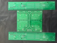
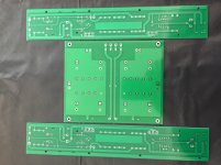
1 set PCB(include a left and Right channel )and CRC supply board.
400VA toroid transformer
Components(see excel sheet)
4U Chassis (either deluxe or Dissipante) with baseplate from DIYAUDIO store.
Good quality drill with bubble level or ideally a drill press
For tapping heat sinks 4 x 40 NC Tap and No 43 Drill Bit with cutting fluid and tap wrench.
A good quality temperature controlled soldering iron")
Starting with heatsink
DIY store heatsinks comes in a plastic wrap; don't unwrap them in a hurry. We needed those plastics to mark things on! or you may have to use masking tapes.
Taping is the most labor intensive process. And if you are careful enough will end up with that DIY satisfaction or in complete despair with a broken tap inside heatsink. So be cautious!!!
Follow this video to the 'T', IT WORKED FOR ME ,so should work for you too. I never tapped anything before this project! It is not that hard.
YouTube
and I used this tap wrench Irwin T-Handle Tap Wrench - TR-1E 0-1/4" - Pipe Wrenches - Amazon.com
Along with Forney 20857 cutting fluid.
See the attached pdf for dimensions and position of drill holes. Position the lower end of boards, edge 3 to 3.5 cm from lower boarder of heatsink.
Please see that hole positions are different for left and right channels in attached pdf.
You can use a permanent marker to draw lines over plastic wrap .Once spots for drilling are marked place the corresponding PCB over and make sure the position is accurate. Don't skip this part. Measure twice and drill once. Those measurements are all in mm. Follow exactly what is shown in video....
The amp PCBs are designed for mounting the JFET/MOSFET on underside of PCB with legs vertical (in contrast to first watt designs). I don't have access to exotic heatsink like Papa does, and this works equally well too.
The mounting hardware is listed in parts list and will provide enough clearance to avoid pins of components from touching the heatsink. (Sorry ,EU fellas, they are in inches).Well ,you can pick the height you want but don't make it more than 1 cm as you may not have enough length for Mosfet pins to get through the holes. Semisouth Jfets however need some trimming of leads. Soldering FETS is the last part so don't solder anything yet.
Mounting holes for FETS are positioned 19 mm from center hole for JFET pins( of the three)and spaced 100mm apart(please see the pdf marked right hole position).
So leave these holes for the last. Once all PCB mounting holes are in place, mount the PCBS .Using a sharp needle mark center pin for both FETs on plastic sheet or masking tape underneath. The FET mounting holes are then marked using scale 19mm vertically from those marking. Again double check before punching hole. Now unmounts PCB and continue with drilling and tapping. Now all holes are ready and keep heatsink aside
Starting a build thread for people who bought PCB from me and for my own future reference.
Will List in this thread materials and tools needed and actual construction in 4 different parts.
Since changing the PCB to UMS specs please see that PCB MOUNTING holes changed from 4-40 to M3 and hence hardware is also changed.
Materials
1 set PCB(include a left and Right channel )and CRC supply board.
400VA toroid transformer
Components(see excel sheet)
4U Chassis (either deluxe or Dissipante) with baseplate from DIYAUDIO store.
Good quality drill with bubble level or ideally a drill press
For tapping heat sinks 4 x 40 NC Tap and No 43 Drill Bit with cutting fluid and tap wrench.
A good quality temperature controlled soldering iron
Starting with heatsink
DIY store heatsinks comes in a plastic wrap; don't unwrap them in a hurry. We needed those plastics to mark things on! or you may have to use masking tapes.
Taping is the most labor intensive process. And if you are careful enough will end up with that DIY satisfaction or in complete despair with a broken tap inside heatsink. So be cautious!!!
Follow this video to the 'T', IT WORKED FOR ME ,so should work for you too. I never tapped anything before this project! It is not that hard.
YouTube
and I used this tap wrench Irwin T-Handle Tap Wrench - TR-1E 0-1/4" - Pipe Wrenches - Amazon.com
Along with Forney 20857 cutting fluid.
See the attached pdf for dimensions and position of drill holes. Position the lower end of boards, edge 3 to 3.5 cm from lower boarder of heatsink.
Please see that hole positions are different for left and right channels in attached pdf.
You can use a permanent marker to draw lines over plastic wrap .Once spots for drilling are marked place the corresponding PCB over and make sure the position is accurate. Don't skip this part. Measure twice and drill once. Those measurements are all in mm. Follow exactly what is shown in video....
The amp PCBs are designed for mounting the JFET/MOSFET on underside of PCB with legs vertical (in contrast to first watt designs). I don't have access to exotic heatsink like Papa does, and this works equally well too.
The mounting hardware is listed in parts list and will provide enough clearance to avoid pins of components from touching the heatsink. (Sorry ,EU fellas, they are in inches).Well ,you can pick the height you want but don't make it more than 1 cm as you may not have enough length for Mosfet pins to get through the holes. Semisouth Jfets however need some trimming of leads. Soldering FETS is the last part so don't solder anything yet.
Mounting holes for FETS are positioned 19 mm from center hole for JFET pins( of the three)and spaced 100mm apart(please see the pdf marked right hole position).
So leave these holes for the last. Once all PCB mounting holes are in place, mount the PCBS .Using a sharp needle mark center pin for both FETs on plastic sheet or masking tape underneath. The FET mounting holes are then marked using scale 19mm vertically from those marking. Again double check before punching hole. Now unmounts PCB and continue with drilling and tapping. Now all holes are ready and keep heatsink aside
Attachments
Last edited:
Power supply board
This PS board can be used with both 120V and 240 Supplies. The board is designed for transformers with dual primary windings of 120V each or single 240V winding.
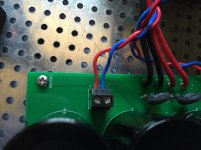
For dual 120V primary such as ANtek AS-4218 just solder primaries to positions marked 120A - 0A AND 120B-0B. Make sure you are using the paired primaries and not the wires from other primary windings. For 120V supply (US) solder two thermistors in positions marked between 120V ON BOARD.
For 240V supply position a single thermistor between position marked 240V.
Beware never fill both positions for 120(2) and 240 (1)thermistors ,it is either 120V or 240V not both.
If you have only single 240V primary transformer just use two side positions (ie 120A and 0B) and no need to use thermistors at this positions.
The position on power supply PCB marked as Bridge gets input from bridge rectifiers and solder holes marked as amp is the DC power supply to amp.
Always make sure of the correct polarity, before soldering or using board connectors.
This PS board can be used with both 120V and 240 Supplies. The board is designed for transformers with dual primary windings of 120V each or single 240V winding.
For dual 120V primary such as ANtek AS-4218 just solder primaries to positions marked 120A - 0A AND 120B-0B. Make sure you are using the paired primaries and not the wires from other primary windings. For 120V supply (US) solder two thermistors in positions marked between 120V ON BOARD.
For 240V supply position a single thermistor between position marked 240V.
Beware never fill both positions for 120(2) and 240 (1)thermistors ,it is either 120V or 240V not both.
If you have only single 240V primary transformer just use two side positions (ie 120A and 0B) and no need to use thermistors at this positions.
The position on power supply PCB marked as Bridge gets input from bridge rectifiers and solder holes marked as amp is the DC power supply to amp.
Always make sure of the correct polarity, before soldering or using board connectors.
Attachments
Last edited:
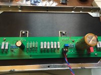
F2/F2J clone PCB
Part values and numbers used are exactly the same as the schematic from First watt site.
If you leave R2 and Z1 unfilled and use the value specified for R6 and use a SJEP120 JFET you will have the F2J. There is an extra resistor pin position marked as J on board at R6 just in case you experiment too much and lift a pad for resistor there.
There extra pads for connecting your boutique capacitors to board by providing solder holes on both sides of capacitors C1 and C2. But make sure the leads are soldered on OTHER sides of C1 and C2 and not on same side(same side pins marked by X on lines) else you will eliminate capacitor from the circuit.
Start soldering 3W resistors first. Use a small cable or copper sheet to provide a uniform clearance while soldering and pull it out after you are done. Leaving a gap under will save board from heat stress.
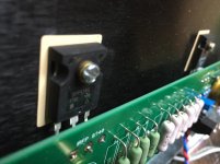
Once everything soldered except FETS position the board on heatsink and screw it tight. Now mount the fets without touching(Bending) their pins and screw them into position.Check for proper alignment before tightening. You should be able to see their pins through corresponding holes.
Now use a sharp pin (I use cut leads from capacitors) and scratch carefully on those pins by inserting the sharp pin through corresponding holes. These marks will serve as the position for bending the leads. Now un-mount FETS by unscrewing and get ready to bend them. I use long noose player but feel free to improvise.
Once both fets ready for soldering loosen up the PCB from heatsink and place the FETS pins into the holes in PCB. they should fit in nicely. Now screw them tight enough to heatsink, maintaining their positions aligned properly with other hand. Don't forget the silpad (Better)or mica grease before doing this.
Now you are ready for soldering fets. This is the method recommended to reduce strain on Fet's pins.
Now connect the powersupply and get ready for biasing.
Part values and numbers used are exactly the same as the schematic from First watt site.
If you leave R2 and Z1 unfilled and use the value specified for R6 and use a SJEP120 JFET you will have the F2J. There is an extra resistor pin position marked as J on board at R6 just in case you experiment too much and lift a pad for resistor there.
There extra pads for connecting your boutique capacitors to board by providing solder holes on both sides of capacitors C1 and C2. But make sure the leads are soldered on OTHER sides of C1 and C2 and not on same side(same side pins marked by X on lines) else you will eliminate capacitor from the circuit.
Start soldering 3W resistors first. Use a small cable or copper sheet to provide a uniform clearance while soldering and pull it out after you are done. Leaving a gap under will save board from heat stress.
Once everything soldered except FETS position the board on heatsink and screw it tight. Now mount the fets without touching(Bending) their pins and screw them into position.Check for proper alignment before tightening. You should be able to see their pins through corresponding holes.
Now use a sharp pin (I use cut leads from capacitors) and scratch carefully on those pins by inserting the sharp pin through corresponding holes. These marks will serve as the position for bending the leads. Now un-mount FETS by unscrewing and get ready to bend them. I use long noose player but feel free to improvise.
Once both fets ready for soldering loosen up the PCB from heatsink and place the FETS pins into the holes in PCB. they should fit in nicely. Now screw them tight enough to heatsink, maintaining their positions aligned properly with other hand. Don't forget the silpad (Better)or mica grease before doing this.
Now you are ready for soldering fets. This is the method recommended to reduce strain on Fet's pins.
Now connect the powersupply and get ready for biasing.
Attachments

Biasing
Ideally need a audio signal generator and oscilloscope for this part. But I used a multimeter to check voltage input and I got 23.5 Volt.
Now use use black probe of your MULTIMETER and touch the ground pin and use red prob and touch the point marked C2 (near IRFP240/SJEP). Turn the blue trimpot to bring the voltage up to 13-14V. Recheck in 35 min again and adjust.(This is what Papa RECOMMENDED). ZM recommended half voltage 11.75 for biasing. 13-14 V mellows things out for me. So I am waiting if someone else can measure using an oscilloscope and update.
Attachments
Thanks for starting this thread Kinku. I’m still honeymooning with my turntable that I just wrapped up a 9 month resto-mod on. It’s nice to just enjoy some music. I’d like to get started on my F2J, but I have a bass project I need to finish for my Oris horns first. Even that looks to be waylaid for the time being. I need to get some work done on the house. The good part about that is that I will be taking on my biggest audio project yet...turning my dilapidated sunroom on the back of my house into a dedicated listening space
A more detailed drawing for holes on DIY store 4U heatsink.Only for right side
For left side follow horizontal positions on pdf for left side and use vertical dimensions from right.
Always place PCB over heatsink and double check screw positions before you start punching holes.
Please scale for the bigger heatsinks.Minimum 4U is a must as they mainatain a temp of 45-50 degree Celsius with 4U heatsinks.
Attachments
ZM, a test tone CD should also work ,right? I am getting a used Tektronic 485 just for this.ZM said half voltage if you have just DVM
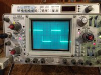
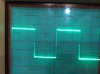
if you have sig gene and scope , set for symmetrical clipping
yup
you don't necessary need dummy load on output for that , but it'll be better to observe clipping with it
ZM please elaborate ,how to do it with dummy load? I guess since wattage is not an issue( 10W) can get a resistor and do it.But how to wire it parallel or series to oscilloscope?
you put resistor instead of speaker
that's called dummy load
it needs to be at least twice of rated amp power
then put probe of scope in most logical way - GND of probe to GND output terminal and positive probe on HOT output terminal
in case that yyou swap scope terminals , scope is on safety GND , amp is on safety GND, in best case mains fuse will go poof!!! , so be careful with scope probe orientation
apply signal , observe on scope output form and set with trimpot that in max output condition flats on top and bottom sine peaks are so-so equal
signal frequency anything between 300Hz and 1KHz

For F2 with flea power it should be no problem putting dummy load but what about bigger amps with 25W and higher output. Is it practical to test these at lower power levels or is there no value in that?
Or do we just use the free dummy tester (me) that my parents gave me (my ears)?
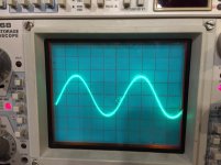
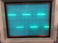
If you don't have signal generator, you can use headphone jack and BNC adapter from computer with Audacity. I just tried this and sine wave is nice, square wave you need to use 'square - no alias'.
Sine wave through cheap 1/8-1/8 headphone cable through 1/8 to rca splitter through rca-bnc adapter at 1KHz

Square wave (no alias)

Or do we just use the free dummy tester (me) that my parents gave me (my ears)?
If you don't have signal generator, you can use headphone jack and BNC adapter from computer with Audacity. I just tried this and sine wave is nice, square wave you need to use 'square - no alias'.
Sine wave through cheap 1/8-1/8 headphone cable through 1/8 to rca splitter through rca-bnc adapter at 1KHz
Square wave (no alias)
you put resistor instead of speaker
that's called dummy load
it needs to be at least twice of rated amp power
I guess the signal quality will depend on your computer and I just thought about whether or not computer output will be high enough to drive an amp to clipping before the sound card runs out of room ...
Anyway, it's better than nothing and you can adjust frequency and wave form through the software and control output from your computer volume.
The software is called Audacity - free, open source project:
Audacity(R) | Free, open source, cross-platform audio software for multi-track recording and editing.
For F2 with flea power it should be no problem putting dummy load but what about bigger amps with 25W and higher output. ...
Dummy loads
review: "Even though rated at 200W, a pair of these handled a 300W/ch amp at full power for well over an hour. Kept my coffee cup nice and hot too."
- Home
- Amplifiers
- Pass Labs
- F2J clone Build thread