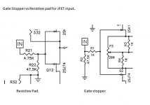
The resistive pad attenuates the signal a bit, while the gate stopper doesn't. With the gate stopper version, you can easily give each JFET its own resistor right next to its gate, which minimizes the chances of parasitic oscillation. Both versions add some noise, which is negligible for line level signals, but not for amplifiers for microphones or phonograph cartridges.
")
I usually move any Gate Stopper resistor to attach directly to the Gate lead.
In this close relationship, the stopper does it's best to ensure the gate never sees a negative impedance and thus usually is a fool proof method of avoiding gate inductance oscillation/instability.
Resistor/s located some distance away from the Gate leadout with long traces/leads will add some inductance to the Gate lead and can make de-bugging of problems later in the build more difficult to find/analyse.
- Status
- This old topic is closed. If you want to reopen this topic, contact a moderator using the "Report Post" button.