Nakamichi PA 5E class A Stasis amplifier hum problem - SOLVED
Hello,
maybe you can help me with a humming about 30 years old Nakamich PA 5 please ?
If i don't connect input cable then there is no hum.
If i connect just one input cable for one side then there is no hum.
If i connect two for stereo input this amplifier makes a hum that you can hear from about 5m distance.
I tryed different cables.
I can connect my smartphone or my TV direct to the PA 5e, all the same hum.
I had only connected the PA 5E to the Power net for testing, nothing else was plugged in,
input with my smartphone and have the hum.
I can also connect the CA 5E II pre amplifier without power plugged in and have the hum.
I tried to use a AC powerfilter with no success.
I bought new 47.000 uf capacitor, no success.
i installed new trimming potentiometer for exactly adjust the bias.
The problem appears when i set the bias to 40mah like the instructions say.
If i set it to zero then there is no hum.
If i use an input filter the hum is gone also with the disadvantage
of worse sound.
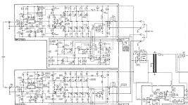
I have attached a screenshot from a part of the circuit plan.
Do you have an idea wich component is maybe broken ?
Best regards from Germany
Edit: Problem solved. Solution on page four.
Hello,
maybe you can help me with a humming about 30 years old Nakamich PA 5 please ?
If i don't connect input cable then there is no hum.
If i connect just one input cable for one side then there is no hum.
If i connect two for stereo input this amplifier makes a hum that you can hear from about 5m distance.
I tryed different cables.
I can connect my smartphone or my TV direct to the PA 5e, all the same hum.
I had only connected the PA 5E to the Power net for testing, nothing else was plugged in,
input with my smartphone and have the hum.
I can also connect the CA 5E II pre amplifier without power plugged in and have the hum.
I tried to use a AC powerfilter with no success.
I bought new 47.000 uf capacitor, no success.
i installed new trimming potentiometer for exactly adjust the bias.
The problem appears when i set the bias to 40mah like the instructions say.
If i set it to zero then there is no hum.
If i use an input filter the hum is gone also with the disadvantage
of worse sound.
I have attached a screenshot from a part of the circuit plan.
Do you have an idea wich component is maybe broken ?
Best regards from Germany
Edit: Problem solved. Solution on page four.
Attachments
Last edited:
you need to do three things.
a.) read D.Joffe's paper
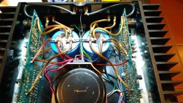
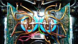
b.) examine the PCB and see how Signal Return is connected to Speaker Return, on both channels. A continuity tester may help trace the routes/connections.
c.) determine if D.Joffe's HBRR & HBRL can be fitted in the voltage reference link between Signal Return and Speaker Return.
a.) read D.Joffe's paper
b.) examine the PCB and see how Signal Return is connected to Speaker Return, on both channels. A continuity tester may help trace the routes/connections.
c.) determine if D.Joffe's HBRR & HBRL can be fitted in the voltage reference link between Signal Return and Speaker Return.
Attachments
")
Is it usual that i can measure with a normal voltmeter 274 Volts AC over the plus and minus from the two 47.0000uf filter capacitors measured in one direction only. The other direction 0V AC.
Or is this causing my hum ?
DC Volts is 124.
The information you give is confusing but those capacitors should not have 274V AC anywhere. The D.C. is o.k. I would first check the bridge rectifier (D401 is it?) I’d want to know that’s ok first - it’s the easiest and most obvious thing to check - if there is indeed AC on the caps.
Is there a way to test it with a multimeter or do i have to order a new one to test ?
Looks like there is AC on the caps, but i can not say if it's only few ripples or much. Is it not normal that i can measure this ripples with a standard multimeter as AC voltage ?
Sorry for confusing.
Looks like there is AC on the caps, but i can not say if it's only few ripples or much. Is it not normal that i can measure this ripples with a standard multimeter as AC voltage ?
Sorry for confusing.
Maybe, but they all look fine. When i measure the smaller capacitors by ohms they go up to infinity. So i think they charge ? I could change them later if there is nothing more suspicious like the rectifier.
I had many years ago a crash. I plugged the input cable in while the amplifier was on and two power transistors where burned and a big resistor exploded. I replaced them but maybe the rectifier suffered from this overload also ?
I had many years ago a crash. I plugged the input cable in while the amplifier was on and two power transistors where burned and a big resistor exploded. I replaced them but maybe the rectifier suffered from this overload also ?
I have changed the rectifier with a 400v 35A but it didn't help to get rid of the hum. I can still measure 271 Volts AC over the capacitors from minus to plus.
As next i try maybe to change the small capacitors and try to use the 10 Ohm Hbr's.
Any more ideas ?
As next i try maybe to change the small capacitors and try to use the 10 Ohm Hbr's.
Any more ideas ?
Attachments
Is it usual that i can measure with a normal voltmeter 274 Volts AC over the plus and minus from the two 47.0000uf filter capacitors measured in one direction only. The other direction 0V AC.
Or is this causing my hum ?
DC Volts is 124.
Something is amiss with the measurement.
One possibility is simply that you are not making a good connection with the meter probes and one is 'floating'.
The problem appears when i set the bias to 40mah like the instructions say.
If i set it to zero then there is no hum.
When you turn the bias up to 40ma then you start to develop ripple on the rails (which is normal) as more current is drawn.
It sounds like you have a ground loop somewhere that is allowing this ripple current to develop a voltage between the inputs, which then gets amplified and becomes audible.
Problems like this can be hard to find.
Have you owned the amp from new and is it totally unmodified ? meaning that it used to be OK and now it isn't.
Something as simple as a ground lift resistor could be the answer but incorporating it is something where you really need to the amp in front of you to see what is going on.
This sounds very like a problem I had on Doug Selfs 50 watt blameless amp many years ago.
Read post #44 and then work back:
3 stage LIN topology - NFB tappings?
Read post #44 and then work back:
3 stage LIN topology - NFB tappings?
I bought it used very long time ago. It was working without hum.
I modified the cables to bigger ones and it was still working.
I remember that the Heatsinks had warm temperature in this time.So bias was set.
Then i made a crash with the input plugged in while the amp was on and i had to change two mosfets and one ceramic resistor from the limiter pcb.
When i remember well the hum was getting louder with the time and one day i opened this amp and lowered the bias even if i didn't knew what i was doing in this time.
I've no magic answer I'm afraid as it would need a detailed look into how the grounding was configured. I think also that you should probably concentrate on setting the bias correctly and then leaving that alone.
You could try as a 'quick fix' (and with no guarantees) adding a low value resistor in series with the signal ground to one channel. Easiest place to do that is at the input socket. Try a 10 ohm 0.5 watt and see if it improves things.
You could try as a 'quick fix' (and with no guarantees) adding a low value resistor in series with the signal ground to one channel. Easiest place to do that is at the input socket. Try a 10 ohm 0.5 watt and see if it improves things.
What I am suggesting you try is this. Just desolder the ground wire from the socket and add a series 10 ohm. It will either make a difference or it wont.
I wouldn't like to advise you to alter grounding within the amp because I'm not familiar with the layout of it all, and it would be easy to cause big problems if something went wrong. Its something you need in front of you to see how its all interconnected and what goes where.
I wouldn't like to advise you to alter grounding within the amp because I'm not familiar with the layout of it all, and it would be easy to cause big problems if something went wrong. Its something you need in front of you to see how its all interconnected and what goes where.
Attachments
Is it usual that i can measure with a normal voltmeter 274 Volts AC over the plus and minus from the two 47.0000uf filter capacitors measured in one direction only. The other direction 0V AC.
You have to get to the bottom of this 247V a.c. You can make progress in this by disconnecting both channels by removing leads 1,2,3 & 4 labeled here:

Now check d.c. and a.c. voltage across C401 you should see 60V d.c. and a few hundred mV or so a.c. - then check same across C402.
When you have good solid + / - 60V d.c. connect up one channel (1,4 or 2,3)
Twiddle with that channel, setting bias and whatever, when you’re happy disconnect it and do the same with the other channel.
This is a basic binary chop procedure after which you’ll have a much better idea what’s going on.
However, as Mooly (no, Mooly not Molly - sorry about that) says, problems like this can be hard to find - more so remotely.
Oh.. and do resist the urge to change components without good reason.
- Status
- This old topic is closed. If you want to reopen this topic, contact a moderator using the "Report Post" button.
- Home
- Amplifiers
- Pass Labs
- Nakamichi PA 5E class A Stasis amplifier hum problem