No it isn’t a reason, it’s an urge.30 years old components should give me a reason")
You think it is safe to remove this cables like you say and turn the amp on ?
Yes - if you understand what your doing it’s perfectly safe. Have a look at the circuit, if you can understand what I’m suggesting you do, you can assess safety yourself. Please don’t do it if you have ANY doubt at all.
The 247 Vac has to be a measurement error or a faulty meter or a bad connection.
If you really did have that AC voltage present then there would be a hole in the ceiling where the caps just exploded through.
Of course there isn’t 247 Vac across the caps - but this is what he says and it isn’t entirely inconsistent with o/c caps is it?
My opinion is that the multimeter is so sensitive that it measures the little spikes from the rectifier as AC voltage or the spikes are bigger and something is wrong.
Well, that’s what we want to find out isn’t it?
And Mooly is quite right, big caps can go off like small grenades, a colleague of mine was deafened for several days when one went off on his bench - it was one hell of a bang. So be warned - they don’t like it up’em!
Thank you, i knew it. This new one's have a protection valve. Maybe this should help to don't explode ?
I will try first the trick with the 10 Ohm hum brake resistor. Some people had success with it.
I have to order them. The circuit from my amp makes it easy to install them i think. Here i found a link to the pdf of the amp: http://www.creapromedia.fr/lesdocs/nakamichi/pa5.PDF
I will try first the trick with the 10 Ohm hum brake resistor. Some people had success with it.
I have to order them. The circuit from my amp makes it easy to install them i think. Here i found a link to the pdf of the amp: http://www.creapromedia.fr/lesdocs/nakamichi/pa5.PDF
Thank you, i knew it. This new one's have a protection valve. Maybe this should help to don't explode ?
I will try first the trick with the 10 Ohm hum brake resistor. Some people had success with it. Here i found a link to the pdf of the amp: http://www.creapromedia.fr/lesdocs/nakamichi/pa5.PDF
Ok Sixtron, I hope it works for you, let us know - and yes, I have already downloaded the PDF.
Meanwhile waiting for the 10 Ohm resistors and small capacitors (i change them also) i have made the test to disconnect the four cables.
Measured voltages:
Left DC 64,7V Right DC 64,5V
AC over both 281V, even if i remove the power cord.
Cables connected:
60,6V and 60,4V
AC 267V
Btw. i had discharged the capacitors after this procedure with an oven lamp.
Bias i had already set before to 40mah like instructions say.
Measured voltages:
Left DC 64,7V Right DC 64,5V
AC over both 281V, even if i remove the power cord.
Cables connected:
60,6V and 60,4V
AC 267V
Btw. i had discharged the capacitors after this procedure with an oven lamp.
Bias i had already set before to 40mah like instructions say.
AC over both 281V, even if i remove the power cord.
Cables connected:
60,6V and 60,4V
AC 267V
What is the a.c. voltage you measure across C401, a) with the meter common connected to ground and b) with the meter live connected to ground.
What are the same measurements across C402 - that is, a.c. across the cap measured both ways.
You can’t have 281V a.c. across a pair of 80V capacitors - not if they’re in working order.
c401 136v AC opposit 0v AC
c402 135v AC opposit 0v AC
The a.c. voltage is problematic but the reverse readings of 0V is makes no sense at all.
Can you confirm your measurements with a scope or another meter?
Failing that I suggest you check your meter by measuring the rectifier a.c. terminals in both directions - as a test. It should read the same a.c. in both directions.
Good - that’s progress.It's the multimeter. I made a test and measured a 1,3v rechargeable battery in AC and it shows 2.1v.
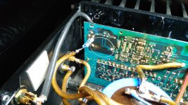
Today i had installed a 5, 10 and 20 ohm resistor from the input ground to the main ground.
The Result:
The hum is gone completely with the 20 ohm resistor. With the 5 and 10 ohm resistor there is a little bit hum remaining, but so few that i don't hear it from sitting on my couch.
The sound changes in this form that if the resistance is higher it's loosing more - i will call it - precision and dynamic for my ears. So i let 5 ohms. See photo.
There is also some kind of few sough from my Tv that is connected to my amp remaining.
It's not the antenna.
Next days i will change the small capacitors and i could order a matched pair of mylar capacitors 10uf 250V from the US made in Taiwan that i will exchange also.
It's part c102 and it's in the input line from the 2SK240.
Btw. before i had changed this capacitor just for testing the sound like some one recommend here in this forum with a bipolar Mundorf capacitor 220uf 63V.
This sounds terrible. The high tones let explode your head so i can not recommend this.
Attachments
Last edited:

Thanks all for help.
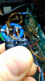
Today i had changed the small capacitors.
Two are looking inflated a little.
For testing i removed the hum braking resistors.
There was the same hum like before.
So it had nothing to do with the capacitors.
I installed the resistors again. This time 3.3 ohm.
This works also. No more hum.
But really i don't understand why in earlier time there was no hum and why today there is hum without the resistors.
Attachments
Perhaps you had a different configuration of equipment and source components using a different combination of mains grounding.
It is always hard to tell from pictures whether a part is OK or not but those caps actually look fine as far as visuals go.
In circuit locations that see a high ripple current it is often the other end of the cap that distorts (where the vent is) as the cap ages and deteriorates.
Do a Bing or Google image search for 'failed electrolytic' to see examples.
- Status
- This old topic is closed. If you want to reopen this topic, contact a moderator using the "Report Post" button.
- Home
- Amplifiers
- Pass Labs
- Nakamichi PA 5E class A Stasis amplifier hum problem