So for me personally, the circuit below would be a good alternative to the output stage of post #26. But then you should not call this M2 anymore.")
Very interesting. Maybe a nice project for autumn
But you should get the MOSFETs now before they become rare.
Patrick
Thanks Patrick
I have curiosity, Although the amplifier has enough power I wonder if I could increase the PSU voltage a bit to get some more power. I have good heatsinks so I don´t think I have problems with the temperature of the Mosfet. I have the Bias configured at 60mA.
I'm thinking of going from 15volt to 16 or 17volt.
I'm thinking of going from 15volt to 16 or 17volt.
Fully agree with ZM.
Unless you have 600R headphones, you already have enough voltage headroom with 15V.
Increasing voltage to even 18V would not bring much benefit.
On the other hand, if you have 30R or 50R phones, you want a lot more bias current.
I usually use 150mA minimum. The DAO is even up to 300mA.
Patrick
Unless you have 600R headphones, you already have enough voltage headroom with 15V.
Increasing voltage to even 18V would not bring much benefit.
On the other hand, if you have 30R or 50R phones, you want a lot more bias current.
I usually use 150mA minimum. The DAO is even up to 300mA.
Patrick
Thanks guys.
So increasing the supply voltage does not have to affect the performance of the amplifier.
I use headphones that range from 30 Ohm to 600 Ohm so I'm looking something that suits all kinds of loads.
At first I also thought about modifying the BIAS and re-using 160mA but I was not sure if I had to modify the voltage supply too.
My "Whammy/Pass ha" (17vDC power supply voltage and 60mA of BIAS) is more powerful than the M2ha.
For the "Whammy/Pass ha" I used 2SK2013/2SJ313 while for the M2ha I used FQP3P20/FQP3N30.

Attachments
Finally I preferred to be a bit conservative. Run with 2R4 Ohm (around 195mA) Now, Mosfets are hot
With headphones of low impedance (and miserable sensitivity like AKG), the amp has been improved a lot.
I have not yet been able to measure its performance with different loads, but I´m sure that it improves with respect to the previous Bias (60mA and 160mA)
With trimpot it is very simple to adjust the offset. I think it's a great improvement.
Next step, add larger heatsinks to the LM3X7 of my PSU.
It has been some time since I adjusted the configuration of my M2ha (BIAS @ 195mA). Where greater differences I have noticed is with low impedance headphones.
My amplifier has almost doubled the voltage since it goes from 60mA to 195mA with loads of 30 to 75 Ohm. With loads over 120 Ohm the voltage has risen a little but nothing remarkable.
I think I´ll leave this configuration definitively.
Now I am assembling the PSU box (I'm going to use two different chassis) but when I bring the Edcor close to the R-core of the PSU, for example if I put one chassis on the other, noise (Humm) is generated due to the transformers interaction. I'm thinking of using a sheet of Mu-metal to wrap in the R-core. Any advice on that? I would not like to cover the Edcor.
Thanks Patrick.
Yes, I have PSU (Trafo+PSU) in a separate box. With a separation of 30 cm the effect is inaudible. I am using a 50cms umbilical cable.
I also think that air is the best insulator, but I have limited space. For this reason I was looking for some trick that would allow me to bring the chassis even closer.
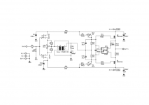
The basic M2 topology is essentially a JFET input buffer, followed by an audio transformer, and then a MOSFET power follower to drive the load.
As already mentioned in post #26, the loading on the input JFETs is quite heavy because they see R6 and R7 in parallel via the transformer. To alleviate this, one can replace R6, R7 through two constant current sources, which have higher dynamic impedance. But in order to avoid unbalanced current leading to DC offset, they need to be equal and to track each other at all times. In the Pioneer SL headphone amplifier, we have proven the stability of a current-mirror based, self-tracking CCS pair. This would be ideal to replace R6 and R7. If one is not worried about voltage headroom, once can improve this even further by using a 4-transistor full Wilson current mirror.
The capacitance of the output MOSFETs appears as additional dynamic load to the JFETs. Thus it is always advantageous to use devices with low (and constant) capacitances to reduce distortion. In that respect, lateral MOSFETs are superior. In the UTHAiM, as well as a recent (not yet published) shootout between the Borbely EB602/200 and a vertical MOSFET equivalent, multiple testers have observed noticeably smoother mids and highs. (No real surprise as Charles Hansen had been telling us all the time.) Also, as we have already discussed at the UTHAiM thread, the lateral MOSFETs have negative tempco at over 100mA bias, and is therefore self-stabilising. This will allow simply using resistors for bias, as in the UTHAiM.
So for me personally, the circuit below would be a good alternative to the output stage of post #26. But then you should not call this M2 anymore.
The 2SK1058/2SJ162 are already NRND, though not yet quite EOL. But the Exicon equivalents are still available and arguably better.
Patrick
could you post the schema in picture or pdf format?
- Status
- This old topic is closed. If you want to reopen this topic, contact a moderator using the "Report Post" button.
- Home
- Amplifiers
- Pass Labs
- M2HA