Hello ")
I would like to open this thread to share experiences and information about the M2 as a headphone amplifier.
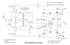
Few months ago while I was work on my F5HA Patrick show me this schematic on M2 thread:
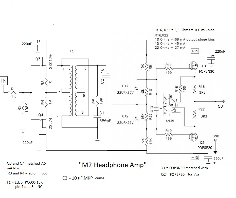
Thanks to WalterW for share the schematic and the idea. I never have work with trafos and I feel curiosity.
A friend and me did some pcb´s and I chose the same PSU that use the F5 HA and a R-core with 2 sec. 15volt@2.1A.
Edit. correct PSU add
My first option was using a high Bias (160mA) and I finded two issues:
First: I start with +-15volt but when I conect both channels voltaje falls to -14,4volt and 14,8volt. I measure 160mA per rail.
Second: Offset is around 400~300mVolt (is to much for headphones)
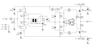
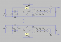
We added a 1K trimpot in series to R6 like original M2 design and we could down the offset but with the same problem with the voltaje rails (I add our schematic).
Reading Nelson's article about the opto, he says that the voltage of both rails has to be exactly the same for the opto to perform its function.
While, the amp sounded well; no noises or hum in my case but with a terrible offset drift and a fully decompensated PSU.
ZenMod recommended me that I changed the bias network for a high value. I changed r6 and r24 (10k for 20K) and Bias fell to 36mA but now amp is very stable with a offset arround 5~1mVolt and both rail work whit +-15dcV. (Thanks Zen)
I has been listening the amp for few hours and is a nice amp. Good sound with low impedance headphone, no noise or hum (I added a ground loop breaker) but... (there is always a but) I would like use it with high impedance headphones too and I´m thinking about change the Bias again.
I don´t know exactly how the amplifier can be kept stable with 160mA but our plan is change r6 and r26 again for 10K and use 10 Ohm value on R16 and R22 for work with 60mA and experiment a bit with the different configurations of BIAS.
I would like to open this thread to share experiences and information about the M2 as a headphone amplifier.
Few months ago while I was work on my F5HA Patrick show me this schematic on M2 thread:
Thanks to WalterW for share the schematic and the idea
. I never have work with trafos and I feel curiosity.A friend and me did some pcb´s and I chose the same PSU that use the F5 HA and a R-core with 2 sec. 15volt@2.1A.
Edit. correct PSU add
My first option was using a high Bias (160mA) and I finded two issues:
First: I start with +-15volt but when I conect both channels voltaje falls to -14,4volt and 14,8volt. I measure 160mA per rail.
Second: Offset is around 400~300mVolt (is to much for headphones)
We added a 1K trimpot in series to R6 like original M2 design and we could down the offset but with the same problem with the voltaje rails (I add our schematic).
Reading Nelson's article about the opto, he says that the voltage of both rails has to be exactly the same for the opto to perform its function.
While, the amp sounded well; no noises or hum in my case but with a terrible offset drift and a fully decompensated PSU.
ZenMod recommended me that I changed the bias network for a high value. I changed r6 and r24 (10k for 20K) and Bias fell to 36mA but now amp is very stable with a offset arround 5~1mVolt and both rail work whit +-15dcV. (Thanks Zen
)I has been listening the amp for few hours and is a nice amp. Good sound with low impedance headphone, no noise or hum (I added a ground loop breaker) but... (there is always a but) I would like use it with high impedance headphones too and I´m thinking about change the Bias again.
I don´t know exactly how the amplifier can be kept stable with 160mA but our plan is change r6 and r26 again for 10K and use 10 Ohm value on R16 and R22 for work with 60mA and experiment a bit with the different configurations of BIAS.
Attachments
Last edited:
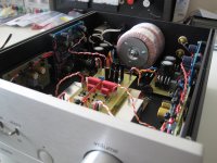
Hi blackdod, strange I didn't have problems with my regulated supply. I used the Jung/Didden super-regulator boards from the store, see pic.
You are right that both rails need to be exactly the same. Any difference immediately results in offset on the outputs. So you have to find out why your PSU is giving that strange different voltages under load.
I also remember that R6 and R24 need to be 10K and almost be matched to have good offset. I won't change them to 20K to change the bias. Change the bias with the source resistors R16 and R22.
Attachments
I was telling that I prefer higher resistance in bias network****
thus R15 and R23 are entirely for removing , and you can use just one cap (preferably higher in value ) between pins 5 and 4 of optocoupler
anyway - when you settle with bias resistors values , for further or finer bias setting ( you need more ) just increase R18 value ...... or decrease source resistors
**** that part of schematic seems to be borrowed from Wayne's HP amp ; he can use lower resistor values there simply because he's driving that node with OP , having much lower Rout than actual arrangement with xformer
go figure .......... maybe I'm just nitpicking ......
Last edited:
Running DC coupled dual rail amps to headphones without protection is asking for trouble - you will always have DC offset unless there’s an auto zero drift servo loop of some sort (or an opamp is used to drive the output stages). Try cap coupling it with a nice back to back 4700uF electrolytic bypass with 4.7uF film cap. You already have a 10uF coupling cap inside Raghu after autoformer so it’s not like this is a pure DC coupled system anyway.
If you want a nice SE Class A amp to drive high impedance phones - no need for an autoformer which just adds third order distortion components and has its own sonic signature of reduced transparency. Think about it, why add an big inductor in front of your HF signals? Go with simple MOSFET follower SE Class A with cap coupling. Or if you like lower distortion try one with an Aksa Lender front end. A small HA MoFo with a good Preamp sounds great too.
If you want a nice SE Class A amp to drive high impedance phones - no need for an autoformer which just adds third order distortion components and has its own sonic signature of reduced transparency. Think about it, why add an big inductor in front of your HF signals? Go with simple MOSFET follower SE Class A with cap coupling. Or if you like lower distortion try one with an Aksa Lender front end. A small HA MoFo with a good Preamp sounds great too.
Last edited:
Jose,
The followers before and after the transformer have reasonable PSRR.
There is IMHO no need to use fancy regulators like the Nazar shunt.
Why not just try a simple LM317/337 regulator first ?
If that works for you at 160mA bias, you have a working system and then can play with other power supply solutions.
As Walter has been successful with the Didden reg, you might want to try that next.
If you want to stay with the Nazar then I would try removing the 4x 220µF electrolytic caps first.
Here is the website for the original Nazar shunt :
http://s-audio.systems/diy/psu-without-electrolytic-eng
Patrick
BTW did you test the regulators on their own with a dummy load (100R 10W) and see if you have the same issue with the voltage sack ?
Also perhaps worth reading my comments before :
Pictures of your diy Pass amplifier
Posts #3616, 3622, 3623, 3625
Patrick
Also perhaps worth reading my comments before :
Pictures of your diy Pass amplifier
Posts #3616, 3622, 3623, 3625
Patrick
> **** that part of schematic seems to be borrowed from Wayne's HP amp ;
> he can use lower resistor values there simply because he's driving that node with OP , having much lower Rout than actual arrangement with xformer
Totally agree.
And because Wayne is using an opamp, it takes care of any DC offset automatically.
When using the transformer, you need to have a trimmer unless both your rails and your MOSFETs are perfectly matched.
And the MOSFETs also need to track each other thermally (e.g. on the same large heatsink).
Patrick
I do not have a Nazar on hand to measure, so instead I ran a Spice simulation for you.
Between no load and 160mA load, the output voltage dropped by ~ 10mV.
So I would suggest you test the regulators on their own first using a power resistor as load.
That will make sure the regulators function on their own.
As already mentioned, I also suggest you test the amplifier with a simple PSU first.
A lab supply, or even 7815/7915 would do.
That will also allow you to test the amp without the Nazar reg.
I would use 20k for R6, R15. R23, R24, and add a 2k trim pot for DC offset trimming.
This is the only sensible solution for your DC offset problem.
And only change bias with R16, R22.
Q1, Q2 on the same heat sink definitely. The larger the better.
That should reduce any DC drifts over time.
I personally would also bypass C2.
Best of luck,
Patrick
Hello
First, thanks to all for help me: Patrick, Zen, Walter, xrk... I read all answer and for me this thread is very instructive.
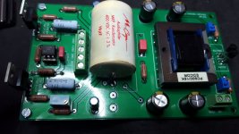
I would like to say that really we use this schematic PSU ( I added file).
Yes, I used mached parts (Mosfet, Jfet and resistors) and a big heat sink for channel.
My friend checked his amp with a cheap PSU and he hasn't problems so we have a problem on our PSU. Probably with the - rail. A badly connected track or a badly oriented transistor.
Although a sophisticated PSU is not necessary, I wanted to use something "elegant" in this amp and how I liked the design you used in the F5HA I wanted to use it here. Yes, yes surely it is unnecessary but... we can
Ok, while my friend check our PSU, I'm working on the Bias network of my M2HA and I've seen Patrick's last post and I'm considering redoing it as he describes it. With this configuration Patrick and taking advantage of the fact that you have the simulation, What value I need for run my amp with 160MA on R16/R22?
I would like to keep C2 cap because IMHO is a distinctive part of this amp (like the trafo).
jose
First, thanks to all for help me: Patrick, Zen, Walter, xrk...
I read all answer and for me this thread is very instructive.I would like to say that really we use this schematic PSU ( I added file).
Yes, I used mached parts (Mosfet, Jfet and resistors) and a big heat sink for channel.
My friend checked his amp with a cheap PSU and he hasn't problems so we have a problem on our PSU. Probably with the - rail. A badly connected track or a badly oriented transistor.
Although a sophisticated PSU is not necessary, I wanted to use something "elegant" in this amp and how I liked the design you used in the F5HA I wanted to use it here. Yes, yes surely it is unnecessary but... we can
Ok, while my friend check our PSU, I'm working on the Bias network of my M2HA and I've seen Patrick's last post and I'm considering redoing it as he describes it. With this configuration Patrick and taking advantage of the fact that you have the simulation, What value I need for run my amp with 160MA on R16/R22?
I would like to keep C2 cap because IMHO is a distinctive part of this amp (like the trafo).
jose
Attachments
> What value I need for run my amp with 160MA on R16/R22?
Try 3.3R first, and the voltage across R16 should be about 0.53 volt.
> I would like to keep C2 cap because IMHO is a distinctive part of this amp (like the trafo).
No, I do not agree.
The output of the transformer is Gnd referenced.
The input of Wayne's follower (as in the shematics in post #1) also need that Gnd reference.
This is especially true when you have Vgs matched MOSFETs.
So the cap does nothing.
You also do not see a cap at the opamp output pin in Wayne's headamp.
The M2 power amp output stage is a different circuit where the cap IS necessary.
You can easily find out for yourself by soldering a temporary jumper across C2.
And then decide for yourself whether you want the extra distortion with the cap.
Patrick
I was just about to say the same thing about removing c2. I would also remove the center connection that joins c17 and c12 to r23 and r15. You should get about 160ma with the 3.3 ohm resistors you are using. It is possible you might get the 160ma's back if you remove the connection. In Wayne's design that connection is used for dc offset but since you use a transformer there is no dc. You could use a jfet op amp to auto adjust the offset, connecting it between the output and the r23 and r15 junction.
Because he was still using 10k for R15 & R23.
This results in only 5V bias for the Fairchild MOSFETs which is of course not sufficient.
In changing R6 & R24, you must also change the values of R15 and R23 by the same amount.
Unless of course you use Toshiba 2SK2013 / 2SJ313, which require much less bias voltage.
But you can readily test all these in LT Spice.
Then you have a good idea what happens by changing which parameter, before you solder anything.
Patrick
This is what I would do if I were to build myself.
Patrick
.
I would like try your idea this weekend and jumper C2 too. Probably C2 only add distortion but for me is funny done this kind of tests.
Answer for Rob; For check it, I only changed R6 and R24 for 20K and I was still using 10k for R15 & R23
Even if the distortion is wrong it is still a very useful tool. When I simulated xrk971's lender headphone amp the distortion readings were very close to his measurements. Then I tried his amp with a mosfet and a larger depletion fet at the output and I got some ridiculously low readings. Under the same conditions it showed 0.00028% thd. the model for the p channel mosfet was from bob cordell and the depletion device model was from the manufacture, it is a sic device. I also tried it using dual supplies with no cap on output with same results.
- Status
- This old topic is closed. If you want to reopen this topic, contact a moderator using the "Report Post" button.
- Home
- Amplifiers
- Pass Labs
- M2HA