Because he was still using 10k for R15 & R23.
This results in only 5V bias for the Fairchild MOSFETs which is of course not sufficient.
In changing R6 & R24, you must also change the values of R15 and R23 by the same amount.
Unless of course you use Toshiba 2SK2013 / 2SJ313, which require much less bias voltage.
But you can readily test all these in LT Spice.
Then you have a good idea what happens by changing which parameter, before you solder anything.
Patrick
In 6L6's original thread on Wayne's headphone amp he states we can use Fairchild or IRF or Toshiba mosfets with the 10K resistor values.
New PassDIY Headphone Amp (Coming Soon)
Is this because the voltage gain is an opamp with a lower output impedance than the transformer?
I am not asking out the kindness of my heart...I have been trying to adapt Juma's current mirror preamp (attached)which sounds great to Wayne's output stage.Kind of a UGS-like situation in where the current mirror frontend will sit on top of the mosfit output stage. I am starting to put it together (I am listening to just Juma's front end now) but now Iam worrying about the resistors...
Attachments
> Is this because the voltage gain is an opamp with a lower output impedance than the transformer?
Yes.
> but now Iam worrying about the resistors...
So what do you think the output impedance of your frontend is ?
Have you done some simulations (or better calculations) to find out ?
On top of that, why would you need to add a buffer instead of change the 2nd stage to high bias ?
And if you must have a buffer, why not use the 2nd leg to generate the bias voltage, like in the UTHAiM with NFB ?
Patrick
> Is this because the voltage gain is an opamp with a lower output impedance than the transformer?
Yes.
> but now Iam worrying about the resistors...
So what do you think the output impedance of your frontend is ?
Have you done some simulations (or better calculations) to find out ?
On top of that, why would you need to add a buffer instead of change the 2nd stage to high bias ?
And if you must have a buffer, why not use the 2nd leg to generate the bias voltage, like in the UTHAiM with NFB ?
Patrick
The output of Juma’s line amp is 250R or so.
I haven’t done simulations...it’s quite a learning curve but I’ve tried to use LTsoice. I need some more time.
I’ve seen you UTHAim. I agree it’s probably the way to go. But I already have Juma’s current mirror built and it sounds good. Basically, I had most the parts to do Wayne’s output stage so why not? Seemed like a good idea at the time. I don’t necessarily need the added current drive but I want to try it with headphones. I’ll read Erno’s pdf although he tends to use a lot more toshiba jfets than I have.
I like to build and try a lot of preamps. Much cheaper and less speaker dependent than power amps.
You missed the point.
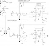
By adding two resistors to the 2nd leg of your preamp, you can generate the bias voltage for a pair of output devices (MOSFETs or BJTs).
I was not asking you to build a Borbely.
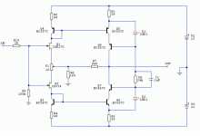
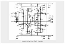
I was asking you to see how Fig. 9 evolved from Fig. 7.
And you can do the same with your preamp and just add 4 resistors and 2 TO220 MOSFETs.
Only my 2 cents,
Patrick
By adding two resistors to the 2nd leg of your preamp, you can generate the bias voltage for a pair of output devices (MOSFETs or BJTs).
I was not asking you to build a Borbely.
I was asking you to see how Fig. 9 evolved from Fig. 7.
And you can do the same with your preamp and just add 4 resistors and 2 TO220 MOSFETs.
Only my 2 cents,
Patrick
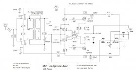
Actually I have to correct myself in post #13.
I overlooked that the secondary of the transformer is connected in series with the primary.
So the impedance of the secondary is not 15k as specified, but 21.6k instead.
The input impedance of the output buffer circuit should therefore not be smaller than 22k.
Hence R6,15,23,24 should be 47k instead.
And even then, the JFETs see a load of 600R, which is quite a lot.
Sorry for overlooking,
Patrick
.
Attachments
You missed the point.
By adding two resistors to the 2nd leg of your preamp, you can generate the bias voltage for a pair of output devices (MOSFETs or BJTs).
I was not asking you to build a Borbely.
I was asking you to see how Fig. 9 evolved from Fig. 7.
And you can do the same with your preamp and just add 4 resistors and 2 TO220 MOSFETs.
Only my 2 cents,
Patrick
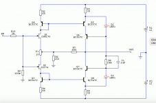
Thanks Patrick.
After reading barbell's article I think I understand. R15/17 for gates. R22/21 for bias. But Borbely is using laterals...for verticals I would need some source resistors too which is not a problem.
Any hints on the value of R22 and R21 for my application?
Attachments
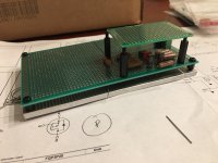
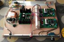
Hello, I'm Fernando, a friend of Jose's. who also is making this amplifier.
I want to thank you for your help. In my case, I was able to solve the problems that I had with my M2HA.
The problem in my case, was on the PSU, I had badly oriented transistor. I fixed and I could set the both rails to +/- 15V. I don't need modify the amplifier, both channels are with 10K in R6, R15. R23, R24, and 3R3 in R16, R22. The DC offset was stable and under control using the 1K trimpot RV1.
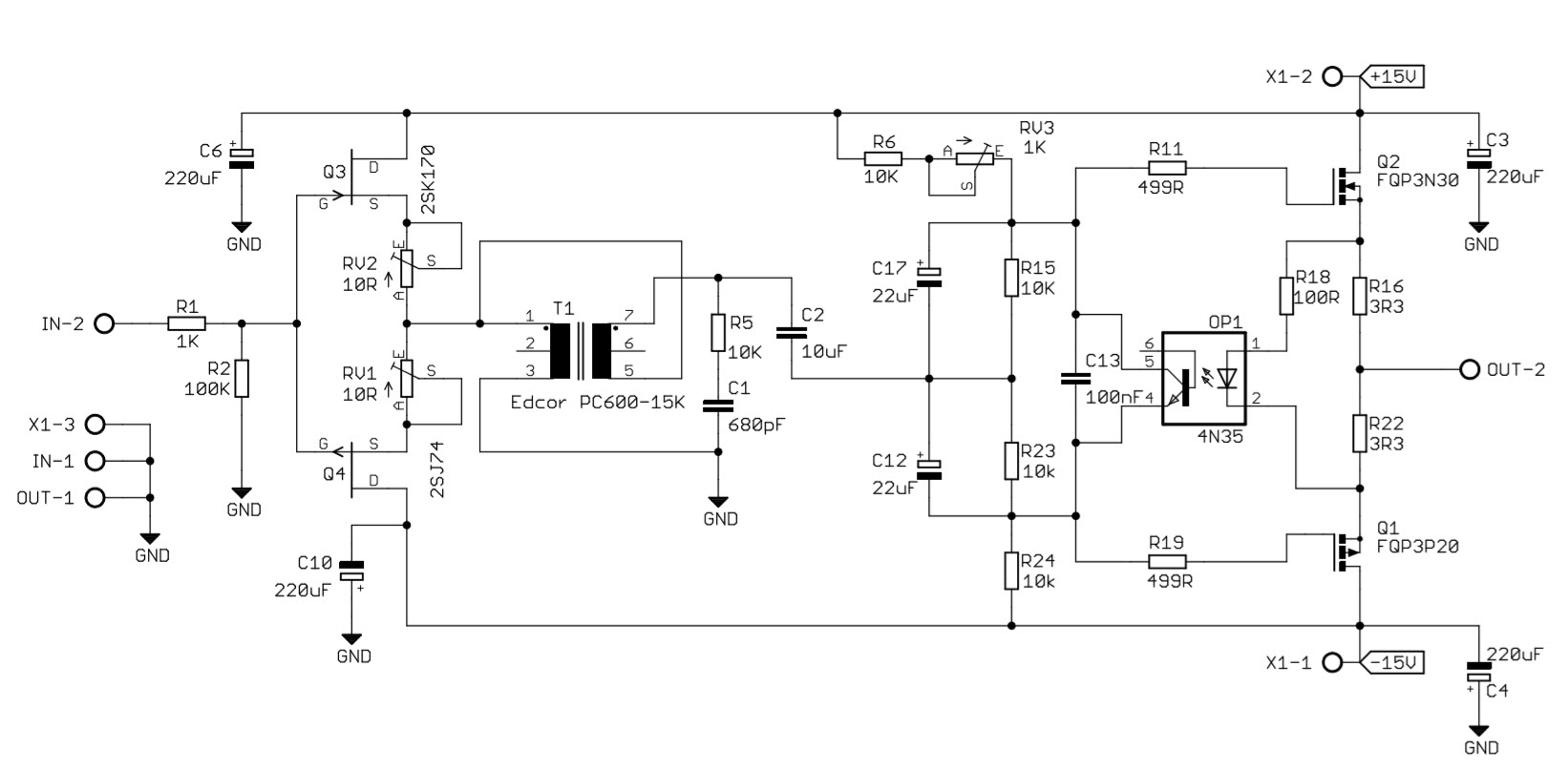
I read all posts, and follow the Patrick recomendation and bypass the C2 and now the sound is more neutral, clear and less distosion, I liked how C2 looked on the amplifier, but sound better without it. Thank you Patrick. I don't understand why in this amplifier is not necesary and in original M2 is need it. I'm clumsy with these things.
In the other hand, If I have free time I want change R6, R15. R23 and R24 to 47K, I'm not sure if R6 and R23 should be a trimpots. I want decrease the bias in the MOSFETs increasing the resistors values R16 and R22, now are 3R3 and the temparture in the heatsink is 51 ºC, we are winter, in summer the tempearature could be increase until 70ºC, I don't want a heat system in the room in summer. Maybe isn't good idea change the bias.
Apologies for my bad english I try to do it the better that I can.
I want to thank you for your help. In my case, I was able to solve the problems that I had with my M2HA.
The problem in my case, was on the PSU, I had badly oriented transistor. I fixed and I could set the both rails to +/- 15V. I don't need modify the amplifier, both channels are with 10K in R6, R15. R23, R24, and 3R3 in R16, R22. The DC offset was stable and under control using the 1K trimpot RV1.
I read all posts, and follow the Patrick recomendation and bypass the C2 and now the sound is more neutral, clear and less distosion, I liked how C2 looked on the amplifier, but sound better without it. Thank you Patrick. I don't understand why in this amplifier is not necesary and in original M2 is need it. I'm clumsy with these things.
In the other hand, If I have free time I want change R6, R15. R23 and R24 to 47K, I'm not sure if R6 and R23 should be a trimpots. I want decrease the bias in the MOSFETs increasing the resistors values R16 and R22, now are 3R3 and the temparture in the heatsink is 51 ºC, we are winter, in summer the tempearature could be increase until 70ºC, I don't want a heat system in the room in summer. Maybe isn't good idea change the bias.
Apologies for my bad english I try to do it the better that I can.
Attachments
> I'm not sure if R6 and R23 should be a trimpots.
Start with 2x 100k 10-turn trimpots near mid-position.
Adjust R6 and R23 so that you get 0V at the transformer output AND the amplifier output.
(Make sure you ground the input first.)
After you are happy the offsets are close to zero and stable, replace them with fixed resistors.
> R16 and R22 now are 3R3 and the temparture in the heatsink is 51 ºC, we are winter,
> in summer the tempearature could be increase until 70ºC, I don't want a heat system in the room in summer.
> Maybe isn't good idea change the bias.
It depends on the headphone you use.
If you use 300R headphones, then 70mA is plenty (7.5R).
If you use 30R headphones then you do want to have 160mA bias.
To reduce temperature, use a more efficient heatsink with vertical fins.
For example Fischer SK47 75mm high.
Fischer Elektronik Profile heatsinks, 1.05 K/W, Aluminium, black anodised SK 47 75 SA | Burklin Elektronik
Patrick
This is also a good example :
https://img.alicdn.com/imgextra/i1/2529159729/TB20kkGeVXXXXaKXXXXXXXXXXXX_!!2529159729.jpg
Patrick
https://img.alicdn.com/imgextra/i1/2529159729/TB20kkGeVXXXXaKXXXXXXXXXXXX_!!2529159729.jpg
Patrick
Thank you Patrick for your help.
When I get the 100k trimpots I'll do the changes that you propouse.
About the bias current, normaly I use both headphoes: 300R and 30R, I'll left the current in 160mA and I'll improve the heatsink as you suggest.
I would like to replace the opto and use a DC servo to automatically adjust the offset, but I do not know how to do it.
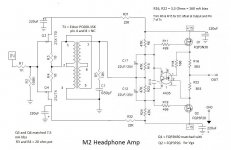
I avoid DC servo if I can.
People who design products include them for product robustness, not for sonic reasons.
But if you must, you may try this.
I have not built myself, so build at your own risk.
You (have to) get your 10µF MKP back.
And there is no need to trim R6 and R23 anymore, just use fixed 47k.
Let us know when you are successful.
Patrick
.
Attachments
Thank you again Patrick.
My first target is the sound quality. If DC servo don't go in that direction I prefer don't use it, but in any case I would like test it for learning purpose, but I have some questions.
-If I get back C2, don't get back the distortion?
-If use DC servo, is the opto mandatory? I don't understand how work the opto, I thought that is for DC offset control, but I don't feel that is working.
Patrick, is that circuit going to have the full gain at the output. I simulated a circuit much like that and with the op amp output connected where you have it I only had a gain of about 1 at the output. I removed c2 and removed the trace that is between the junction of c12, c17 and the junction of r15, r23. Then I connected the op amp output to the junction of r15, r23 and it worked. I also place a small cap to ground after r42.
> I removed c2 and removed the trace that is between the junction of c12, c17 and the junction of r15, r23.
I cannot see why that should matter.
And for me C2 is necessary to block off the Tx from the opamp output.
But maybe you have a different explanation ?
> I also place a small cap to ground after r42.
That I certainly would not do.
Patrick
I cannot see why that should matter.
And for me C2 is necessary to block off the Tx from the opamp output.
But maybe you have a different explanation ?
> I also place a small cap to ground after r42.
That I certainly would not do.
Patrick
Last edited:
Patrick, is that circuit going to have the full gain at the output. I simulated a circuit much like that and with the op amp output connected where you have it I only had a gain of about 1 at the output. I removed c2 and removed the trace that is between the junction of c12, c17 and the junction of r15, r23. Then I connected the op amp output to the junction of r15, r23 and it worked. I also place a small cap to ground after r42.
well , If you have more of these funny mushrooms , feel free to share .........

- Status
- This old topic is closed. If you want to reopen this topic, contact a moderator using the "Report Post" button.
- Home
- Amplifiers
- Pass Labs
- M2HA