Thanks for input.
Is there a performance benefit of 15V with LED vs 18V without LED?
Also, I am thinking to install a 317/337, pre-regulator set at +/-24V, and using the positive leg to supply the LX mini x-over. That keeps ac out of Whammy chassis and reduces stress on +/-18V supply.
LX mini current draw is so low that there should be no unbalancing of Whammy supply.
I use the 78/7915 regs with green LEDs 2.2v and the OPA2134, runs great.
Just waiting for my blue 3mm LEDs to arrive for a power indicator, where would be the best pick off point and what value resistor.
I followed the little circuit on post #93 by HiGHFLYiN9s. See my post #207 for my execution. I can't remember what value resistor I used but you'll probably want to experiment anyway to get your desired brightness.
V- at -23 v ?
Sincere Thanks to everyone involved in this project.
I started my build yesterday. I plugged in today and no blowing up or smoke. good. However
V+ seems ok at close to 17V
V- is about -23V
Is this ok or should I debug before going further? V- LED stays brighter longer than V+ LED, after disconnecting, for minutes. Both are red.
In addition to power supply, C3 C4 C8 C9 C10 C28 are stuffed with 100uf/25v (what I had in the box). The only other change from suggested components: Using 5 Ohms instead of 5.1 Ohms for R20 R21 R37 R38.
Thanks in advance for help.
LED Staying Bright for Longer on Switch off
bajjisw
You should have similar V+ and V- after the regulators measuring from the unused resistor pads. The V+ looks right but the V- is too high. It looks like the V- regulator isn't regulating.
I have the same problem with my V+ LED. Despite having 'correct' voltages and having changed out regulators, LEDs and diodes my V+ LED still stays bright for over a minute after switch off. I can't see any reason why that should be normal, but have so far not been able to find anything wrong that could be causing it. I even swapped out the transformer for another I had lying around to eliminate it !
Sincere Thanks to everyone involved in this project.
I started my build yesterday. I plugged in today and no blowing up or smoke. good. However
V+ seems ok at close to 17V
V- is about -23V
Is this ok or should I debug before going further? V- LED stays brighter longer than V+ LED, after disconnecting, for minutes. Both are red.
In addition to power supply, C3 C4 C8 C9 C10 C28 are stuffed with 100uf/25v (what I had in the box). The only other change from suggested components: Using 5 Ohms instead of 5.1 Ohms for R20 R21 R37 R38.
Thanks in advance for help.
bajjisw
You should have similar V+ and V- after the regulators measuring from the unused resistor pads. The V+ looks right but the V- is too high. It looks like the V- regulator isn't regulating.
I have the same problem with my V+ LED. Despite having 'correct' voltages and having changed out regulators, LEDs and diodes my V+ LED still stays bright for over a minute after switch off. I can't see any reason why that should be normal, but have so far not been able to find anything wrong that could be causing it. I even swapped out the transformer for another I had lying around to eliminate it !
I would assume it is from all the capacitance in the ripple filtering stage. Adding a resistor across V-/V+ and ground will drain off the capacitance faster. Perhaps someone can recommend an ideal resistance here?
bajjisw
You should have similar V+ and V- after the regulators measuring from the unused resistor pads. The V+ looks right but the V- is too high. It looks like the V- regulator isn't regulating.
I have the same problem with my V+ LED. Despite having 'correct' voltages and having changed out regulators, LEDs and diodes my V+ LED still stays bright for over a minute after switch off. I can't see any reason why that should be normal, but have so far not been able to find anything wrong that could be causing it. I even swapped out the transformer for another I had lying around to eliminate it !
Thanks for the responses. My first attempt at a response was snafued. I guess it did not post. Apologies if it shows up twice.
I read the one month I missed in this thread, and my issue seemed similar to #508. So, I decided to take out the LEDs and use the voltage divider instead. Voltages seem ok now.
V+ 21.7V (at R35)
V- 20.4V (at R36)
This is on the black board.
For completeness, measurements with LEDs below (Lite-On Inc. / LTL2R3KRD-EM). On a scope, the voltages looked beautifully flat. The magnitude was off. I used surplus transformer from the guide, 18V secondaries.
On 7915, Output=-19.8V, Input=-27.7V
On 7815, Output=14.9V, Input=27.7V
This also "solved" my LED issue.
")
Would a 3A rated pushbutton be sufficient for the mains input on the traffo?
Just purchased my PCB. Can't wait to put it together.
I built a SE BA-3 a few years ago, so this should be a walk in the park.
You are toggling AC, which is far easier than DC. If it is rated for 3 amps DC, then that should be more than enough.
So, I have a question.
When I first built this amp, I threw in a TL072 since I had one on hand, and I noticed a little low end distortion. Like a fuzziness, almost like crossover distortion or clipping. However, when I replaced it with a OPA2134, the problem vanished.
I don't think it is giving the TL072 a fair chance in this amp, is there anything specific I should adjust for the TL072(or any other op amps I try in the future with similar problems)?
Measurements looked good with a TL-072 and it sounded okay. The OPA is probably a better choice though.
Maybe it's just the sound of the op amp. Is the TL072 generally 'noisy' on low frequencies? I don't really know where to start diagnosing it, but if it is a weird one, I can record the output and check the waveform to see exactly what is going on.
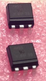
Vishay opto coupler 4n35
Which is pin 1 ?
I don't see a dot. The notch along the side of the package is similar to the build guide I hope. Meaning the V marks pin 1 ?
Reference:
http://www.vishay.com/docs/83717/4n35x.pdf
Sorry about the fuzzy phone pic.
Which is pin 1 ?
I don't see a dot. The notch along the side of the package is similar to the build guide I hope. Meaning the V marks pin 1 ?
Reference:
http://www.vishay.com/docs/83717/4n35x.pdf
Sorry about the fuzzy phone pic.
Attachments
Thanks for the quick reply. And thanks for the amp.
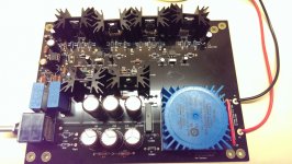
With a LM4562, output offsets are
L -1 mV
R 0.8 mV
I'm tempted to call it good and stop fiddling. Any thoughts?
Missing headphone jack, input and output wiring. Hopefully soon. I surprised myself by not cannibalizing cords.
Though I am an ME by education, I seem to forget to check mechanical dimensions.
Attachments
Thanks for the quick reply. And thanks for the amp.
With a LM4562, output offsets are
L -1 mV
R 0.8 mV
Though I am an ME by education, I seem to forget to check mechanical dimensions.
I went with the same OpAmp. I'm an ME too, but find my self dabbling in electronics as a hobby.
- Home
- Amplifiers
- Pass Labs
- "WHAMMY" Pass DIY headphone amp guide