Hi All,
I plan to build the attached circuit for use with an Ipod touch (max. output ~1Vrms). I plan to use 24V laptop chargers but as I have multiple 19.5V, I will try it with these first. When the first channel is up then I will build up the second channel and buy the 24V adapters. I have shamelessly copied from others and I trust that this is seen as the sincere form of flattery that it is.
Bias current is planned at ~2.7-3A and this gives up to 130W of dissipation on the 2sk180 (rated 300W). I have significant mass of heatsink available. 24V, 5A adapters are available at reasonable cost or alternately 19.5V, 6.7A ones could be used instead.
However, before I put start depreciating parts with solder and expose myself to needless expense of make a silly error, I thought I would expose myself to ridicule instead... Please can the assembled cast of characters review the attached and make sure I am not proposing anything particularly stupid?
I realize that the high resistance bias adjustment pot will limit the speed at which the power supplies can charge the caps on the floating section of the circuit, but I don't see a good way around this. It does concern me that the bias wont come up as fast as the main rail across the Vfet, but I have included the CL-110 which limits the max current during startup to 3A. So I am hoping that this will prevent any smoking until the bias is established.
I am in the Portland, OR area and if there is anyone around that has access to scopes and analysers I'd be delighted to visit with said toy to take some measurements and potentially optimize this.
With much appreciation to Nelson Pass and all who contribute,
thanks
Beardy
ooooo! UPS man just arrived with a heavy box...
Attachments
And in a triumph of plagiarism and blind luck it seems to work…
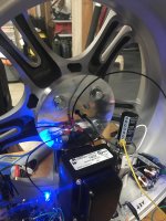
After another look at the M2 schematic and a highly scientific Brownian motion approach to using LTSpice I realized I had the wiring around the transformer wrong and so I attach the revised schematic. It uses two laptop supplies for the main current source and a couple of 24V wall warts for the buffers / voltage gain stage. I did run into an issue when adjusting the bias as one of the supplies just cut out. I had to stop and wind the bias back right down and turn it all off. After pizza it came back up OK so I guess that the bricks were just turning themselves off, perhaps due to over current protection…
It sounds great despite indifferent old speakers and a crappy source. I will build up the other channel.
The DC resistance of the 193V was measured at 2.5-2.6ohms using a Fluke DVM. I assume that this is DC measurement, but it appears way out from the Hammond 15% tolerance on the 1ohm DCR specs s I wondered if the Fluke is doing something odd… can anyone shed any light on this?
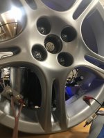
At 4.7V across the inductor the case of the 2sk180 is sitting at 130F/54C and the center of the wheel is nice and warm. The back of the mounting plate (inside the wheel), is in the 90sF (ambient 55F). I assume this is comfortably low for the chip and figure I can push it up towards 80C..?
After another look at the M2 schematic and a highly scientific Brownian motion approach to using LTSpice I realized I had the wiring around the transformer wrong and so I attach the revised schematic. It uses two laptop supplies for the main current source and a couple of 24V wall warts for the buffers / voltage gain stage. I did run into an issue when adjusting the bias as one of the supplies just cut out. I had to stop and wind the bias back right down and turn it all off. After pizza it came back up OK so I guess that the bricks were just turning themselves off, perhaps due to over current protection…
It sounds great despite indifferent old speakers and a crappy source. I will build up the other channel.
The DC resistance of the 193V was measured at 2.5-2.6ohms using a Fluke DVM. I assume that this is DC measurement, but it appears way out from the Hammond 15% tolerance on the 1ohm DCR specs s I wondered if the Fluke is doing something odd… can anyone shed any light on this?
At 4.7V across the inductor the case of the 2sk180 is sitting at 130F/54C and the center of the wheel is nice and warm. The back of the mounting plate (inside the wheel), is in the 90sF (ambient 55F). I assume this is comfortably low for the chip and figure I can push it up towards 80C..?
Attachments
Last edited:
You probably didn't miss anything. I am a complete novice. I am not sure there is a `point' but I can tell you how I got here...
I had just built the ACA from parts and I was late to the party and missed the Sony Vfet build opportunities. I could not find pairs of Sony Vfets for sale at reasonable prices, but I was able to get hold of some larger 2sk180s. Nelson Pass had noted that he intended to bring another single ended design to the collective and had already posted designs for the big 2sk77. Later he posted
“I am currently listening to this (attached)
I spent a lot of time messing around with LT Spice, reading and asking questions and Nelson and others were kind enough to leave a lot of breadcrumbs as well more direct guidance. The key points are:
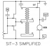
Common drain appears to offer lower noise than common source, noting that single ended doesn’t offer the cancellation you can achieve with push pull, Nelson’s posting of the above SIT-3 confirmed this was a/the preferred approach.
I wanted to use an Ipod as a source which has limited voltage swing (1V rms) and I wanted more voltage gain than could be achieved with the transformer used in the M2. I am using an Edcor PC10k/150 (backwards).
If I modelled the SIT-3 with a 2sk180, I lost all the high frequencies unless I used a second buffer after the voltage gain. Nelson stated that these larger devices need more drive and ZM confirmed a second buffer was a kosher approach.
Given the inefficiency of the SE configuration I was drawn to the advantages of inductive loading so I read lots from MR and his MOFO.
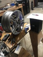
I wasn’t sure I could do a nice job and so I wanted to build this first attempt for my garage/shop rather than living room, so I built one channel using a convenient chunk of aluminium as a heat sink.
Nelson stated that Vfets have poor rejection of noise on the drain and so I added filtering to the SMPS, but I ran into predictable over current issues on start up. SMPS go into hiccup mode if I try to start them at full bias, so I will be employing aggressive use of thermistors to reduce the inrush current.
What can I say… I’m delighted that it makes a nice noise.
I had just built the ACA from parts and I was late to the party and missed the Sony Vfet build opportunities. I could not find pairs of Sony Vfets for sale at reasonable prices, but I was able to get hold of some larger 2sk180s. Nelson Pass had noted that he intended to bring another single ended design to the collective and had already posted designs for the big 2sk77. Later he posted
“I am currently listening to this (attached)
I spent a lot of time messing around with LT Spice, reading and asking questions and Nelson and others were kind enough to leave a lot of breadcrumbs as well more direct guidance. The key points are:
Common drain appears to offer lower noise than common source, noting that single ended doesn’t offer the cancellation you can achieve with push pull, Nelson’s posting of the above SIT-3 confirmed this was a/the preferred approach.
I wanted to use an Ipod as a source which has limited voltage swing (1V rms) and I wanted more voltage gain than could be achieved with the transformer used in the M2. I am using an Edcor PC10k/150 (backwards).
If I modelled the SIT-3 with a 2sk180, I lost all the high frequencies unless I used a second buffer after the voltage gain. Nelson stated that these larger devices need more drive and ZM confirmed a second buffer was a kosher approach.
Given the inefficiency of the SE configuration I was drawn to the advantages of inductive loading so I read lots from MR and his MOFO.
I wasn’t sure I could do a nice job and so I wanted to build this first attempt for my garage/shop rather than living room, so I built one channel using a convenient chunk of aluminium as a heat sink.
Nelson stated that Vfets have poor rejection of noise on the drain and so I added filtering to the SMPS, but I ran into predictable over current issues on start up. SMPS go into hiccup mode if I try to start them at full bias, so I will be employing aggressive use of thermistors to reduce the inrush current.
What can I say… I’m delighted that it makes a nice noise.
Attachments
Use a cap multiplier with a simple mosfet to have slow startup on smps startup. A simple one like Juma cap Mx is what I have after everyone of my smps for Class A amps.
Juma's Easy-Peasy Capacitance Multiplier
Use IRFP240 for positive rail and IRFP9240 for negative rail. You really should run this amp on single polarity with DC step up from 24v to 50v.
DC DC boost converter Constant Current Mobile Power supply 250W 10A LED Driver | eBay
These are very low noise boosters.
- Status
- This old topic is closed. If you want to reopen this topic, contact a moderator using the "Report Post" button.
- Home
- Amplifiers
- Pass Labs
- 16W Ipod inductively loaded 2sk180 source follower