It's been a while, but I'm back.
Here's a little thing I thought I would share. It's actually going to be used on a chineseium Douk 2.1channel amp with 4 LM 3886 chips, but what I'm sharing is an inexpensive way to make what I think will be a decent heat sink.
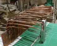
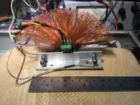
Copper is one of the best conductors of heat out there, and it's easy to work and join with solder. I had a chunk of 1/8" x 2" bar and 400MCM cable, and thought what a unusual but possibly quite effective material for a heat sink.
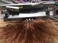
So, going from memory, it's about 9" long chunk of bar with (you count them) a bunch of pieces of 10ga solid copper wire about 6" long. They're all lined up, then soldered to the bar. I used plumbing flux and nolead solder and a map gas torch, but you could use a large wattage iron. I fluxed and clamped all of the wires with a bar of aluminum so it wouldn't stick, then heated and soldered. After it cooled, I sand washed, then sand blasted and coated with a thin coat of aerosol poly. Last, I drilled and tapped holes for mounting.
I'll let you know how it works...
Here's a little thing I thought I would share. It's actually going to be used on a chineseium Douk 2.1channel amp with 4 LM 3886 chips, but what I'm sharing is an inexpensive way to make what I think will be a decent heat sink.
Copper is one of the best conductors of heat out there, and it's easy to work and join with solder. I had a chunk of 1/8" x 2" bar and 400MCM cable, and thought what a unusual but possibly quite effective material for a heat sink.
So, going from memory, it's about 9" long chunk of bar with (you count them) a bunch of pieces of 10ga solid copper wire about 6" long. They're all lined up, then soldered to the bar. I used plumbing flux and nolead solder and a map gas torch, but you could use a large wattage iron. I fluxed and clamped all of the wires with a bar of aluminum so it wouldn't stick, then heated and soldered. After it cooled, I sand washed, then sand blasted and coated with a thin coat of aerosol poly. Last, I drilled and tapped holes for mounting.
I'll let you know how it works...
Attachments
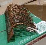
Copper doesn't anodize so well, but the sand blasting put a matte finish to it. No, I wouldn't try to make polished heat sink.
As for thermal transfer between bar and wires, there's 1" of solid solder connecting them. 5" of wire would be well into the area of diminishing returns if it was forced air, but I don't think so for natural convection. They will be oriented in the way they are pictured with the wires over the board a few inches.
I'll do a little calcs on actual surface area. That's one of the main drivers of heat removal.
")
Hi Brian,
Thanks for sharing, your copper bar is in my wishlist, hihi
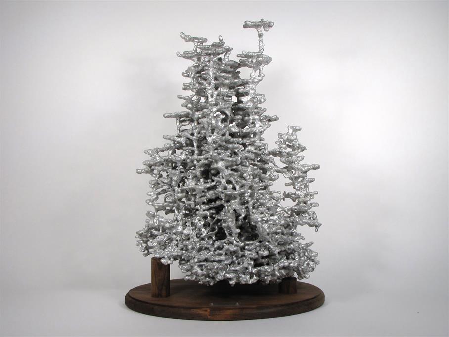
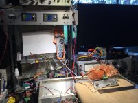
I’ve got my test done
Ambiance = 28 C
Aluminium clamp to MOSFET case = 50 C (stabilised)
Power dissipation to device = 19W
Heatsink
Copper multistrand monster cable
Length = 10cm
Size = 250 AWG
Strand = 575
I am too dump in math to get the dissipation surface
But can measure the air exchange area
14 x 10 x5 in cm
Pretty amazing
Pascal
Thanks for sharing, your copper bar is in my wishlist, hihi
I’ve got my test done
Ambiance = 28 C
Aluminium clamp to MOSFET case = 50 C (stabilised)
Power dissipation to device = 19W
Heatsink
Copper multistrand monster cable
Length = 10cm
Size = 250 AWG
Strand = 575
I am too dump in math to get the dissipation surface
But can measure the air exchange area
14 x 10 x5 in cm
Pretty amazing
Pascal
Attachments
I like these innovations, thanks. Again, without doing the maths, my first reaction is that the wires probably don't need to be that long........I'm guessing that given the small diameter they will have been most effective in thermal dissipation in the first couple of inches.......but I'm open to correction on that point.....
Any more wacky ideas out there?
To rework a proverbial saying: "Living in a sub-tropical climate is the mother of invention."
Any more wacky ideas out there?
To rework a proverbial saying: "Living in a sub-tropical climate is the mother of invention."
Mosfed-
I love the look of the bushy top. In your case, I think it could be that the wires are too thin to transfer heat all the way to the end for maximum heat dissapation/copper mass, but no doubt enough to do the job, and the density of the bush could act as insulation by congesting the air flow, but the real test is how hot does the device get per it's dissipation. And like me you didn't drop $200 on pretty aluminum extrusion. But I think you should house the rest of the amp in a doll with the 'fet in the head. You also have a fair sized chunk of aluminum also acting as heat sink.
I saw on Ebay, a chinese LED headlight retrofit that used a 6" or so braided ground strap like wire as a heat sink.
After work I was lacking motivation to look at the device. I already have the board mounted with heat sink grease and all. so I'll have either run the amp with a know signal and level to calc the power put into the sink. It's 4 pcs LM3886, so rough equivalent to 240WRMS of class AB. I forget, but worse case in burnt enregy is somewhere around 2/3 rated output, and then the amp is dissapating around 1/2 the 240W.
Under worse case, I'm OK with 70 deg C, or 45 deg rise, I'll need .375 degC/W to keep out of thermal shutdown. After I get the rest up and running, I'll dummy load it and see where it goes the report back.
Edit-
levistubby-
You made me wounder, so I looked up the thermal conductivity of the solder (plumbing solder, no lead, is 98%tin and 2%silver IRRC) relative to the copper. Tin is only 1/6th as effective at thermal transfer as the copper (better than 60/40 solder though), but the geometry of the solder joint puts a large surface area with little space between the wire and bar. The trasfer between the 2 should be at least as good as down the length of the wire. Maybe it could have been better if I TIG welded it, but my TIG welder is only 150A. Copper is such a good conductor I don't think I have the amps to do it.
Last edited:
There will be little or no direct contact between the copper plate and the rods. I assume that the thermal conductivity of lead free solder is less than copper.
If I was trying to make a heat sink of that sort I would use a plate thick enough to be able to drill deep holes in its edge and then push in tight fitting rods. In that way there would be good thermal contact between the the plate and the rods.
If I was trying to make a heat sink of that sort I would use a plate thick enough to be able to drill deep holes in its edge and then push in tight fitting rods. In that way there would be good thermal contact between the the plate and the rods.
It's not as good of a co0nductor but the surface area connecting the rod to the bar is huge with respect to the crossection of the rod. And the solder joint will be as good as any mechanical joint, and much better than a "tight" fitting rod. If I was money, I could use silver solder. It's the only metal with a better transfer characteristic.
Copper doesn't anodize so well, but the sand blasting put a matte finish to it. No, I wouldn't try to make polished heat sink.
But you can do something similar : expose the shine cooper for some seconds to ferric chloride (usually used for pcb making).
The resulted surface will dissipate better the heat.
Re Surface finish of heatsinks
Don’t get too distracted by thoughts of the surface finish of heatsinks. At the temperatures and temperature differentials we are operating at, the overwhelming heat transfer mechanism is convection, with very minor contributions coming from radiative transfer, and the surface finish is what affects the radiative transfer efficiency. Since black anodizing is cheap to do with aluminum and maximizes the radiative transfer, most heatsinks are anodized to get the last extra percent of thermal efficiency. In what we work with, the difference between a shiny metal heatsinks versus a matte black finish will maybe yield a difference of 0.5 to 1 deg C in operating temperature at best.
Don’t get too distracted by thoughts of the surface finish of heatsinks. At the temperatures and temperature differentials we are operating at, the overwhelming heat transfer mechanism is convection, with very minor contributions coming from radiative transfer, and the surface finish is what affects the radiative transfer efficiency. Since black anodizing is cheap to do with aluminum and maximizes the radiative transfer, most heatsinks are anodized to get the last extra percent of thermal efficiency. In what we work with, the difference between a shiny metal heatsinks versus a matte black finish will maybe yield a difference of 0.5 to 1 deg C in operating temperature at best.
Aluminium works well for fins with a thickness to length ratio of ~1:10
you can stretch this to about 1:15, but you will find that the ends of these fins are considerably cooler than the main bulk, i.e. the extra length does not add much dissipation capability.
Copper can do 1:15 effectively and I suspect that 1:20 falls into the same problem where the extra length does not add much extra cooling.
This all changes in forced air cooling.
One sees aluminium out at 1:25 and at much smaller air gaps. This makes for small and light sinks in comparison to convective/passive air cooling.
A 0.5mm copper wire could be good at 10mm long (1:20).
How much better would the sink be if the wrire lengths were doubled to 20mm long (1:40)? and what about 100mm long(1:200)?
Excellent! Here's the technical discussions I was hoping for.
Yes, copper has almost double the thermal conductance of aluminum. So if the optimum thickness to length ratio is 1:10, copper should be around 1:18 or so. This relation works for fins, but with wire, that doesn't exactly hold true. The real mechanism is surface area to cross section area which translates length to thickness with fins. Also note the r-theata isn't directly proportional to height. There's a diminishing return as fins get taller.
Based on 50 wires at 5", I'm calculating about 100 in^2 of effective surface area if the conduction is good enough to carry heat all the way to the end.
Also with the staggered wires instead of flat long fins, I'm thinking maybe the induced airflow will be less laminar and better able to pull the heat from the surface.
Enough speculation. I need to get some hard data.
Good to see you're still around, Metalman.
- Home
- Amplifiers
- Pass Labs
- DIY heatsink