Started in the "complementary Zen v5" thread by Greg ( got to a few harsh words but i think that is sorted out by now) we are ( at least ) two ampbuilders that would like more power. Since i first posted a note on the v5 i´ve built a mono pair and used them for my RCF L12P48 sealed bass units. This sounds great, but when i put my old Accuphase p300 at the same work this sounds a lot more powerful. So if we want to make a high power amp based on v5 topology, which way is right?. Increasing rail voltage seems a limited travel direction as we pretty soon reach max power dissipation if we want to keep idle current at 2A or thereabout.
Looking for complementary N and P fets at higher power rating only leads to switching devices, APT types for instance that have totally ridicoulus ratings, but it seems as soon as You cross the 30amp/250w line there is very high input capacitance values so they dont seem to be suitable. Bridging then? As input is floating it seems easy but looks like a differential amp made out of two separate complementary amps, will this work?. As i like these v5´s i would be gratefull for tips before blow them up in a stupid tryout. Or is it better to rework the v5 to semicomplementary as n devices with higher power ratings are plentifull. Obviously these questions are somewhat directed to Mr Pass but any and all comments will be sincerely appreciated
Looking for complementary N and P fets at higher power rating only leads to switching devices, APT types for instance that have totally ridicoulus ratings, but it seems as soon as You cross the 30amp/250w line there is very high input capacitance values so they dont seem to be suitable. Bridging then? As input is floating it seems easy but looks like a differential amp made out of two separate complementary amps, will this work?. As i like these v5´s i would be gratefull for tips before blow them up in a stupid tryout. Or is it better to rework the v5 to semicomplementary as n devices with higher power ratings are plentifull. Obviously these questions are somewhat directed to Mr Pass but any and all comments will be sincerely appreciated
Intending to post schematics
I´ve toiled with this more power topic a little while and would like to propose a bridged setup for the Zen v5. This will ofcourse consist of redrawn schematics of Nelson Pass´s v5 design so i would like to check if there is any objection to the posting of my idea of this sidetrack. Will need lots of advice but my RCF 12" realy do work better with heavy stuff behind.
Pls advice if this is ok or not.
Re: Intending to post schematics
")
I'm not Mr. Pass but this might be the answer you are looking for: http://www.diyaudio.com/forums/showthread.php?postid=361537#post361537ingvar ahlberg said:
Pls advice if this is ok or not.
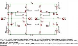
So for us who feel the need for more power but would like to stay with very simple circuits. This is what i had in mind. Original schematic is here:http://www.passdiy.com/pdf/zen-v5-hires.pdf. At 40-50V rails there will be 100W, or slightly more, output power obtainable. This amp will need a lot of cooling. It will be a bit cumbersome to adjust as You need to set idle current, adjust DC offset both ref to ground and between +/- outputs. Input signal should be balanced. Power supply should be common for the "halves" to minimise drift so this will be a huge supply. Psrr should be better than for original i think but not tested yet. I´ll start geting power supply toghether and try one chanel first. All opinions apreciated!
Attachments
My intention is to use this with my RCF L12P48 12" drivers wich are housed in 130l closed cabinets. Active x-overs, will be used up to 100-120, or parallell with Fostex Fe103Z up to said f and letting the Fostex continue to ~ 1500 where original Zen takes care of the AMT´s. Impedance of RCF is 8 ohm but a large coil sends alot back so one should regard it as 4 i think.
Looking for a bit of tutorial
Hello Grey.
Wondering a bit about the bias issue, there´s (quite) a few things i dont fully understand. Looking at the original Zen v5 at, say, 30V rails one would regard this as a 25W amp. If biased at 1A/ device it would clearly be within pure class a operation. According to article 2-2,5A/device has a lot less distortion and sound better, which would have to do with intrinsic unlinearitys in mosfets. Is this related only to current or is it a function of idle power? As p-mosfets with higher power rating than IRFP9240 are rare this sets the limit of this bridge v5 and also leaves something to be desired in safety margins.
- Status
- This old topic is closed. If you want to reopen this topic, contact a moderator using the "Report Post" button.
- Home
- Amplifiers
- Pass Labs
- Power hungry Zen v5 builders