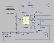
I made sim with SJDP
tonight with SJEP , OK ?
Thanks , sir
But how can I search for SJEP with the same vgs as IRFP ?
you need SJDP if you want to pair it directly , without additional bias circuit , and I can't tell you is that even possible , because I didn't make any analysis regarding biasing voltages at desired current
make distinction between enhancement devices (SJEP , IRFP) and depletion devices (SJDP , JFets) ......... then you'll understand why you need SJDP for possible direct pairing with IRFP
make distinction between enhancement devices (SJEP , IRFP) and depletion devices (SJDP , JFets) ......... then you'll understand why you need SJDP for possible direct pairing with IRFP
SEF
this one goes in prototype
Zen Mod, I experimented with your SEF circuit. I left R7 at 220E as in original M2. R1 & R2 was made by a string of 0.18E X 3, 5watt each. But they got too hot in just a few minutes.
I couldn't get offset below 4 volts. Hence, used a 4700uF cap to connect the speaker.
Sound was fuller, more organic, forward and airy. But the liquid character of M2 was sacrificed.
Comments.
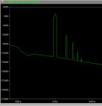
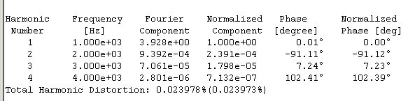
any of these amps made with DEFiSIT as role model , will have greater THD than M2 , so it is logical to sound less clean , erring on sweet side
regarding values in any of shown sim schematics , they're exactly that - simulations , so some value tweaking in vivo is inevitable
setting correct Iq ( look at Pd per device - 35 to 40W) and offset is trivial thing , done in 20min or so
so , fear no more but no less , you'll need to wait for (slow) Mighty Moi , to show in vivo values , in case that you can't fix them by your self
Thank you Zen Mod for your response. I could try setting offset etc. What is the dissipation in R1, R2 & what wattage would be appropriate? Thanks.
everything is on schematic
top of R1 is 1.01V , bottom of R2 is 3.8mV
so , I=U/R
1.01/(2x0R27)= 1A87
dissipation in resistor P=I^2 x R
P=1A87^2 x 0R27=940mW
3W resistor will do
so , you need to have one voltmeter across any of 0R27 to observe and set Iq , and second voltmeter across output to observe and set offset
write here what your results are and I can tell more precise what to do
Sorry to quote a relatively old post, but the "1, 2, SIT3" thread triggered me to ask again.
I have some 2SK180D, that gives Id of around 1.5A at Vgs of -3.2V (Vds=20V), would they be feasible devices for the DEFiSIT. (attached are the measurements of the 2SK180D).
Hi cwtim, please switch in your curvetracer picture from the SK180 the "load conditions" button for me so I can see the real conditions you used.
The conditions shown are possible not the ones necessary for a measurement.
Please for me, I want to measure some parts from my basement too.....

I'm still waiting to read your further impressions with these (well defined)
A SIT-1 amp is the best amp I heard up to now. That is not only my opinion, but my friends, even those with ears like a bat, say this.
Those liking valves say it is at the same level like their best amps.
Happy guys who have one.
May I add, I am really a bit embarrassed that SIT-3 can go to the same level.
A PP with a Sit for the pos wave form and a mosfet for the neg part.
How can the wonderful sound of a SIT be there when only the left ear hears the SIT.....
I have no doubt that SIT-3 sounds wonderful!

But I do not understand it or I can not explain it.

Zen Mod, I get your point about offset - going back to schematic in post 264, if Trimpot R12 doesn't get rid of offset, depending on polarity, R6/R13 need to be resized.
But what controls Iq, other than R1, R2?
voltage sag across two 0R26 resistors is feeding opto LED , opto LED is controlling "openess" of opto BJT
current through two 0R27 resistors tends to rise ,LED shines brighter , BJT is more open , more current through resistors up and bellow ,more voltage across them , thus squeezing mosfet gates closer ........ closing them for current
simple , isn't it ?
A SIT-1 amp is the best amp I heard up to now. That is not only my opinion, but my friends, even those with ears like a bat, say this.
Those liking valves say it is at the same level like their best amps.
Happy guys who have one.
May I add, I am really a bit embarrassed that SIT-3 can go to the same level.
A PP with a Sit for the pos wave form and a mosfet for the neg part.
How can the wonderful sound of a SIT be there when only the left ear hears the SIT.....
I have no doubt that SIT-3 sounds wonderful!
But I do not understand it or I can not explain it.
only possible explanation - all of these are born under the same Hat
(and Hat belongs to most wakoo Mad Hatter
 )
)Can the Lundahl LL1517 trafo be used here or in B1 with gain?
http://www.lundahl.se/wp-content/uploads/datasheets/1517.pdf
I am using this now with very good results....gain set to 12dB (1:4)....but I have a couple of questions:
1.
Output impedance should be buffer impedance times gain squared? With buffer 5R this would be approx. 80R. But I measure around 230-250R?
With gain changed to 18db (1:8), it should be approx. 320R. But I measure around 600R?
Is it becauce I also must consider the Rdc of the windings? Or other losses?
2.
I have found others using a RC-compensation load on the LL1517 across the secondaries (10nF+680R).
When using as repeater, do I still only use these compensation values accross the "secondary" windings? Or accross the whole span?
I do not have a scope to tune values...
- Home
- Amplifiers
- Pass Labs
- Most Greedy Boy, of them all... or (there is no) DEFiSIT of Papa's Koans