did something .... though no way that I can wrap my head about that , at least not in this moment
it'll work , at least semi-decent , as this :
though , there must be more elegant ways ( and we know there are , even if I can't remember where they're posted
Hi Zen Mod and all.
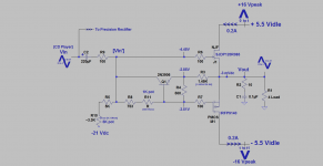
The attached schematic is today's Best DEF amp on the bench. I hope that it complements the objective results you already found from running the .asc file which is attached to the parent post.
1. PNP [2N3906] operates in the Common Base configuration. Its Vbe 'samples' Vgs of P-MOSFET. The magnitude of Vgs inherently controls or [reflects] the magnitude/value of its drain current. The fate of this drain current of P-MOSFET becomes/is part of the current which flows through the loudspeaker load.
2. Thus PNP via its [varying] Vbe senses current flowing through the load.
3. The collector current of PNP [Ic] is separately controlled by its Vbe.
4. Thus the magnitude of [Ic] of PNP is related/proportional to the current flowing through the load.
5. PNP does not invert the phase of the signal at its emitter [same as phase as that at Vout]. It also has Power Gain.
6. The power gain of PNP enables the bootstrapping of [Vin]. The output signal at its collector [Vin'] is in phase with the CD player's input signal [Vin]. [Vin'] pushes back against [Vin] such that the load presented to [Vin] becomes higher than it is.
7. The power gain of PNP enables Positive Current Feedback [PCF]. This is manifested by [Vin'] having a larger magnitude than that of [Vin].
8. Can get bootstrapping with a capacitor between Vout and Vin [per Mr. Pass]. But it cannot grant this amp PCF [no gain from cap] which is the forte of this circuit using PNP.
9. PCF intrigues us. Mr. Pass uses it in F7 which delivers great sound. He also teaches the value of PCF in his patent US 4,899,387. A device to manage and eradicate standing waves which populate the listening space and are concentrated in its corners.
10. Based on point #9, the loudspeaker load [ADS L730] of this system sits in a convenient corner of the listening room. It is used as a sound generator and a suppressor of standing waves.
11. I sit [~ 28 feet away] and listen to its [plenty] sound at the opposing corner. This system generates superb sound. A deep and articulated base [no/negligible mud] plus high detail throughout the spectrum. This is a consequence of the power and value of DEF-PCF in my musical experience.
Best
Anton
Attachments
One more detail...
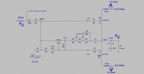
Hi Zen Mod and All. The attached schematic completes the aforementioned application. Here are its new details:
1. Please ignore my unusual PSU for this DEF amp. I'll revert to the original standard fixed conditions taught by Mr. Pass.
2. I partitioned the emitter resistor of PNP [1.45K] which I showed in the previous post into 4 others. They must add up to 1.45K so as to keep the parent idle conditions for sonic comparison.
3. This action allows for "increasing' the power gain of PNP and thus increasing the extent of its Positive Current Feedback [PCF] as mirrored by the magnitude of [Vin'], and possibly further bootstrapping the input signal [Vin].
4. The capacitor [220uF] shorts the music signal which develops across one or two out of the three [470 Ohm] resistors as shown by using the [Switch]. This increases the gain of PNP; but without affecting its biasing scheme and that of DEF.
5. My loudspeaker [ADS L730] is a 3-way. Its woofer crosses into the next driver at ~700 Hz. AC-shorting only one 470 Ohm emitter resistor gives this system great sound without loss of sound pressure.
6. AC-shorting [simply move cap on proto-board] two out of the three 470 Ohm emitter resistors of PNP reduced [noticeably] sound pressure. Too much of the good PCF in my system is bad. It affects the woofer which happens to carry more valuable musical information outside its "woofing" 30 to 100 Hz. range. It could have overly suppressed the normal flow of the input signal [Vin].
7. Point # 6 shouts clearly. PNP generates PCF and has valuable sonics. I believe that the proper extent of PCF in my application [via experimentation and Spice] also alleviates the listening space from the ill-effects of standing waves. . By the way, there is absolutely no reason not to relocate my loudspeaker anywhere else in the listening space.
Best
Anton
Attachments
Mea Culpa for my mistake..
Hi Zen Mod and All,
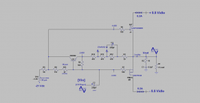
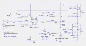
I apologize for this error in the schematic of my last post. I have failed to notice the destination of the input coupling capacitor [220 uF] for a while now. Thus, my explanation of the working of its circuit are now suspect and need to be re-interpreted.
The correct schematic is attached. Please note that the input coupling capacitor at [Vin] went directly to P-MOSFET, and not to the input of R085 as taught by Mr. Pass. This is the arrangement which gave me the subjective performance I reported. Its observations are still good.
NB. I made the same error as above in the schematic I posted in the DEF thread in my last and recent reply to generg. My apology again.I'll clean it up...
Best
Anton
Hi Zen Mod and All,
I apologize for this error in the schematic of my last post. I have failed to notice the destination of the input coupling capacitor [220 uF] for a while now. Thus, my explanation of the working of its circuit are now suspect and need to be re-interpreted.
The correct schematic is attached. Please note that the input coupling capacitor at [Vin] went directly to P-MOSFET, and not to the input of R085 as taught by Mr. Pass. This is the arrangement which gave me the subjective performance I reported. Its observations are still good.
NB. I made the same error as above in the schematic I posted in the DEF thread in my last and recent reply to generg. My apology again.I'll clean it up...
Best
Anton
Attachments
just take care of fact that your arrangement is perfectly good for your wakoo ways of modulating that output stage , while for more usual ways (buffer in autoformer ) , input impedance of OS is important thing
Thanks ZM for your advice. My posts have strayed [unfortunately] from the core and parent themes of the threads which discuss DEF, DEFiSIT, and Most ..Koans etc. threads. I will park future circuits of these hot topics as their applications in the Class aP amplification thread.
Best wishes
Anton
no need for that (re-parking somewhere else)..... more we brainstorm (anywhere) , better for Greedy Boyz , not mentioning benefits for actual brains involved ")
besides , as you can see , I'm pretty much etalon for bad ideas throwing around , so whatever you post , you're automatically clever

besides , as you can see , I'm pretty much etalon for bad ideas throwing around , so whatever you post , you're automatically clever
no need for that (re-parking somewhere else)..... more we brainstorm (anywhere) , better for Greedy Boyz , not mentioning benefits for actual brains involved
besides , as you can see , I'm pretty much etalon for bad ideas throwing around , so whatever you post , you're automatically clever
Hi ZM. Thanks for your encouraging post. I'll stay on the [fun] path of my old posting practices. But I'll be more vigilant and focused for everybody's sake..
Best
Anton
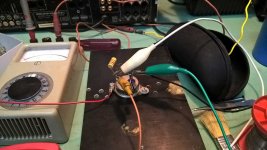
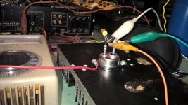
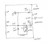
as I already wrote somewhere , had them yesterday on the bench , to check Vgs needed for 1A, 1A5 , 1A8, 2A
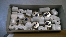
didn't bother with exactly temp. controlled conditions , more was interested in range of Ugs and , of course , confirmation that my Buddy didn't got duds
so , I'm gonna squeeze that optocoupler in-between the gates of big bad one and wimpy mosfet
didn't bother with exactly temp. controlled conditions , more was interested in range of Ugs and , of course , confirmation that my Buddy didn't got duds
so , I'm gonna squeeze that optocoupler in-between the gates of big bad one and wimpy mosfet
Attachments
as I already wrote somewhere , had them yesterday on the bench , to check Vgs needed for 1A, 1A5 , 1A8, 2A
didn't bother with exactly temp. controlled conditions , more was interested in range of Ugs and , of course , confirmation that my Buddy didn't got duds
so , I'm gonna squeeze that optocoupler in-between the gates of big bad one and wimpy mosfet
Hi ZM, What is your target current and supply voltage?
DEFiSIT taste without Source R
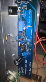
I did some trick after Nelson's confirming and Claudio52's explanation.
Anyway, it seems to work, and I like the sound that feels more true to the music with finer details.
I am sure there are DIYers of my kind who has limited skill. But I enjoy what I can do. This way I can just replace 2Sk82 with THF-51 or other SIT and adjust the Iq and Vgs..
Until the time when Zen Mod or others give something easy for me to read and build, I think I can play with this one.
Attachments

Here is a circuit that should allow one to adjust for Vgs mismatches between the SIT and the PFET without using source resistors. It does not attempt to change the transconductances of either FET. (I also posted this in the DEF Amp thread #320).
Attachments
Here is a circuit that should allow one to adjust for Vgs mismatches between the SIT and the PFET without using source resistors. It does not attempt to change the transconductances of either FET. (I also posted this in the DEF Amp thread #320).
I am collecting the parts for your circuit. Thank you again Lynn. As I remember, you already tried this.
Can I use the "LINEAR SYSTEMS MATCHED LSJ74/LSK170 JFET PAIRS (GRADE B)" from the diyaudio strore?
SUFI-SIT resolved ........ kind of
I had a dream ............ no , wrong start
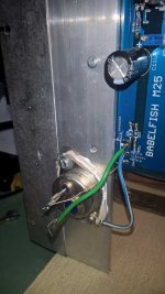
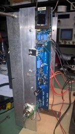
I had a big dilemma last night - trying to nest THF51-S in SEF amp concept , where upper part is having source resistors and optocoupler (biasing main device ) is fed on them ........ or to nest it in Babelfish M25 concept , so no source resistors and where optocoupler is fed from Hall current sensing chips in rails
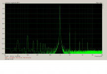
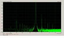
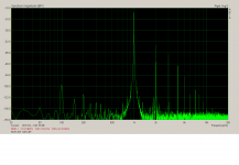
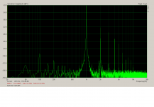
first one is having lesser THD , accordining to sims ;
second one is having greater THD, again according to sims , but higher level of purity , rawness , call it whatever you want ..... sans source resistors it is closer to Papa's most wakoo one - DEFiSIT amp
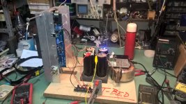
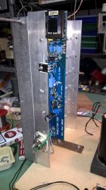
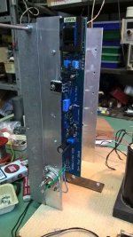
so , this morning decided to try it thrown in Babelfish M25 cradle ......
I had a dream ............ no , wrong start
I had a big dilemma last night - trying to nest THF51-S in SEF amp concept , where upper part is having source resistors and optocoupler (biasing main device ) is fed on them ........ or to nest it in Babelfish M25 concept , so no source resistors and where optocoupler is fed from Hall current sensing chips in rails
first one is having lesser THD , accordining to sims ;
second one is having greater THD, again according to sims , but higher level of purity , rawness , call it whatever you want ..... sans source resistors it is closer to Papa's most wakoo one - DEFiSIT amp
so , this morning decided to try it thrown in Babelfish M25 cradle ......
Attachments
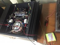
-
 WP_20180807_19_42_20_Pro.jpg83.3 KB · Views: 11,107
 -
 WP_20180807_19_41_51_Pro.jpg68.4 KB · Views: 11,056
 -
 WP_20180807_19_41_35_Pro.jpg80.5 KB · Views: 11,121
 -
 WP_20180807_19_41_20_Pro.jpg91.4 KB · Views: 11,146
 -
 WP_20180807_18_07_00_Pro.jpg85.6 KB · Views: 11,163
 -
 WP_20180807_18_06_56_Pro.jpg75.9 KB · Views: 11,392
Last edited:
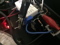
little trouble , who could expect that ........ sims aren't so precise regarding biasing network resistor values (few important factors missing in models , most important of them being gate leakage current)
so , had to heavily alter some resistor values - against values predicted by dummy sims made by even dumber operator , but solved it
I'm pretty satisfied , THF51-S not exactly being PapaSIT (read - made for sissy audio purposes) , but real tough welding drek
........ sims aren't so precise regarding biasing network resistor values (few important factors missing in models , most important of them being gate leakage current)so , had to heavily alter some resistor values - against values predicted by dummy sims made by even dumber operator , but solved it
I'm pretty satisfied , THF51-S not exactly being PapaSIT (read - made for sissy audio purposes) , but real tough welding drek
Attachments
- Home
- Amplifiers
- Pass Labs
- Most Greedy Boy, of them all... or (there is no) DEFiSIT of Papa's Koans