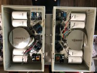
Thanks for replying.
Yes I’m looking at removing the 0.47 Ohm resistors and replacing with a coil for CLC.
So asking if the coil I listed is a good fit and where in the path to insert it? Or other?
Thanks.
If you're going with the coil, just replace the 0R47 resistors with it. It's going to whack the ripple so hard that the capacitance imbalance before/after the coil won't matter.
Whether or not it's the right coil I couldn't tell you. Still coming up that learning curve myself.
Hahaha, been there, I've done the same with six heatsinks, don't remember the line in the middle on my sinks.
Weird thing is that they deliver the heatsinks with that coating on it, making this heatsinks almost impossible to function right.
Do you think it is a kind of anodizing layer or do you think its is a coating?
I ask because a normal anodized heatsink, has a more mat black look, this is a kind of glossy anodized layer.
The cabinetry of the console will be built around this base in a way that unless you knew how it was built you wouldn’t know it was there, so no need to plane or finish. Although it will get a couple coats of sealer.how will you plane the base of the console with the steel strips?
Thanks for asking.
I’m not a expert on coatings by any means, but I don’t think it’s anodized. Like you say, anodizing has a more matte sheen. This coating is shiny very black and consistent, actually I like the look better than anodized. Should stay clean easier too. But it is pretty hard. Can’t even scratch it very easy. If I had to guess, and I’m guessing, I’d say it’s some kind of ceramic based coating.Hahaha, been there, I've done the same with six heatsinks, don't remember the line in the middle on my sinks.
Weird thing is that they deliver the heatsinks with that coating on it, making this heatsinks almost impossible to function right.
Do you think it is a kind of anodizing layer or do you think its is a coating?
I ask because a normal anodized heatsink, has a more mat black look, this is a kind of glossy anodized layer.
Most coatings would ball up and/or leave traces when sanding, when I hit it with the angle grinder sanding disk it turns to fine dust. After seeing that is when I put on the respirator.
Hahaha, been there, I've done the same with six heatsinks, don't remember the line in the middle on my sinks.
Weird thing is that they deliver the heatsinks with that coating on it, making this heatsinks almost impossible to function right.
Do you think it is a kind of anodizing layer or do you think its is a coating?
I ask because a normal anodized heatsink, has a more mat black look, this is a kind of glossy anodized layer.
I remember reading that crossover coils such as the one you listed were not the best choice for CLC PSU's. I can't remember the thread or the post, but I remember may people recomending the hammond chokes as the go to choice for CLC applications.
Check the 159 and 195 series from hammond:
Hammond Indutores fixos | Mouser Portugal
Spent some time today over at the cabinet shop.
A week ago I laid up the floor, plenty enough time for all the glue and adhesive to cure. To test the design I put 1 1/2” strips on each end and put 100 lbs of weight in the middle to set how much sag. Right at 1/16”. Not bad. In actuality, after the cabinet is built and screwed down it will add strength too.
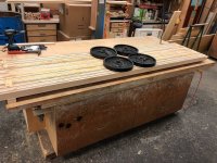
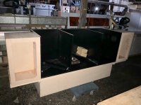
Then cut up some shop ply with black liner, ran it through the edge bander and assembled the basic form. Starting to take shape. But then somejone must have hit a pole as all,the power went out. So I cleaned up and went home to work on the heat sinks.
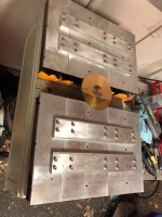
I had already picked up a 10/32 gap and stainless screws to bolt up the heat sinks. So a bit of time I have the first channel ready to attach to the chassis.
A week ago I laid up the floor, plenty enough time for all the glue and adhesive to cure. To test the design I put 1 1/2” strips on each end and put 100 lbs of weight in the middle to set how much sag. Right at 1/16”. Not bad. In actuality, after the cabinet is built and screwed down it will add strength too.

Then cut up some shop ply with black liner, ran it through the edge bander and assembled the basic form. Starting to take shape. But then somejone must have hit a pole as all,the power went out. So I cleaned up and went home to work on the heat sinks.

I had already picked up a 10/32 gap and stainless screws to bolt up the heat sinks. So a bit of time I have the first channel ready to attach to the chassis.

what drivers and preamp will you use?
For the preamp I’ll be using my McIntosh C2300.
I’m building the speaker cabinets generic. In the picture above you can see that the face has a large cutout. This face is kind of a sub baffle. The finish baffle will be made to fit whatever drivers/combo’s I might want to play with.
The cabinet measures 24” tall x 12 1/4” deep x 14 1/2” wide as you see in the pic. Walls are 3/4” shop ply. There will be bracing and since the cabinet will be built into another cabinet, the walls will ultimately be 1 1/2” thick.
But first up will be a pair of JBL LE8T’s. I purchased them a couple of years ago for another speaker project. I had them completely rebuilt, new cones, surrounds and had the magnets recharged.
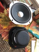
A console is a very big compromise, especially since this one will have a turntable. I’m hoping that with the mass of the cabinet, amp, and the bracing/thick walls on the driver, that vibrations will be limited getting to the turntable.
Thanks for asking.
And sitting to each side of this console will be a pair of self powered subs.
Continued working on the amps today. Switched the door swing and latch from top/bottom to the sides. Finished bolting the second channel heat sinks together and got them mounted to the doors. When I mount the heat sinks to the doors for the last time I will space the heatsinks off the doors about 3/16”. This will be the exit path for the air pushed in by the fan. Hopefully this will keep some of the heat from transferring to the chassis and then into the console.
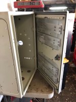 g
g
So far exactly 100 tapped/bolted points.
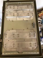
Then, using the cutout pieces from the doors, I made patch panels for the existing holes. Cut the holes for the fans and drilled the hole to bolt the transformer.
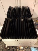
Now that the heavy duty work is done I can start locating the rest of the power supply.
 g
gSo far exactly 100 tapped/bolted points.

Then, using the cutout pieces from the doors, I made patch panels for the existing holes. Cut the holes for the fans and drilled the hole to bolt the transformer.

Now that the heavy duty work is done I can start locating the rest of the power supply.
A slow work week, so got to spend the day drilling and tapping, yay!
First monoblock complete ready for wire
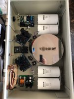
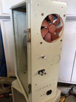
I know, ugly industrial chassis. But after it is slipped into the rear of the console only the edge of the heatsink will be visible. But due to the weight of the transformer and heat sinks this heavy duty enclosure is great. And it’s already powder coated!
First monoblock complete ready for wire


I know, ugly industrial chassis. But after it is slipped into the rear of the console only the edge of the heatsink will be visible. But due to the weight of the transformer and heat sinks this heavy duty enclosure is great. And it’s already powder coated!
Not ugly at all! It fits the requirements perfectly!
What the PSU in the bottom of the picture for?
Regarding the vibration management for the turntable you can always make a spring loaded sub base or better yet, you could "float" the turntable above the console with a wall mounted shelf.
What the PSU in the bottom of the picture for?
Regarding the vibration management for the turntable you can always make a spring loaded sub base or better yet, you could "float" the turntable above the console with a wall mounted shelf.
Not ugly at all! It fits the requirements perfectly!
What the PSU in the bottom of the picture for?
Regarding the vibration management for the turntable you can always make a spring loaded sub base or better yet, you could "float" the turntable above the console with a wall mounted shelf.
Thanks for your post.
That is a 12v supply to run the fan, the relay’s that drop out the MS35’s on delay after startup, and the “power on” relay. My preamp sends out a 5v signal that I take advantage of to turn the amps on, no independent power switch.
Turntable isolation. So I’m trying out an idea on this console. I don’t think I have read about consoles with mass. And a “typical” turntable has low weight, so springs are a good solution. But my turntable weighs over 65lbs, springs to carry that weight would also transfer vibrations and may even pick up some?
So my first try is overbuild the cabinet section for the drivers, and the rest with mass. Right now just the console bottom weighs about 120 lbs, when complete I estimate the cabinet itself will weigh 180 lbs. then the amps probably weigh close to 100lbs each. So the turntable will be sitting on a mass of over 380lbs. The shelving that will be holding up the turntable inside the cabinets has some sound isolation ideas and the turntable itself has Stillpoint isolation feet.
If that doesn’t work, I designed the amount of shelves and spacing to accommodate a Minus K.
All that mass will be affected by the 8inch bass drivers. You might not feel the console vibrating or moving, but there will be micro vibrations moving all around. Since you have many different materials the resonance frequencies should be broad and not affect any particular range. Experimentation will certainly be needed! Fun times ahead!
ps: thanks for the info on the minus k, never heard of them and the products really seem interesting!
ps: thanks for the info on the minus k, never heard of them and the products really seem interesting!
All that mass will be affected by the 8inch bass drivers. You might not feel the console vibrating or moving, but there will be micro vibrations moving all around. Since you have many different materials the resonance frequencies should be broad and not affect any particular range. Experimentation will certainly be needed! Fun times ahead!
ps: thanks for the info on the minus k, never heard of them and the products really seem interesting!
Thanks for commenting. Yes I looking forward to see how it’s plays out.
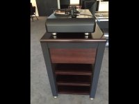
Here is a pic of the turntable stand I built for a friend of mine. Made of stainless steel, Mahogany w/Stillpoints for his Artisan Fidelity modified SP10 M3. That turntable plinth was CNC’d out of a solid block of aluminum, and weighs over 100 lbs.
Behind the wood panels hides the Minus K. There is a 3/16” gap between the Mahogany top platform and the SS rack, the Mahogany platform is actually sitting on the Minus K. Just the weight of an album closes that gap by 1/16” it’s so sensitive.
Good way to hide the ugly Minus K!
Amp progress has been on delay, waiting for wire order to arrive. Last build was kind of a mish mash of what I had on hand. This time I ordered all sliver plated copper stranded with Teflon insulation. Gauges 22, 20, 16, and 14. The 22 and 20 is coming from an industry guy and made by Beldon. The 16 and 14 is made by Alpha off of eBay. Should be here Monday.
So a couple nights this week I went over to the cabinet shop. Laid up the veneers on 3/4” shop ply one night and this afternoon went over and made the rough cuts for the main outside cabinet and then the doors. This is my first time laying up plywood/veneer, way more work and harder than I thought, and this with all the right tools. The cabinet body is Wenge and when finished should look like this;
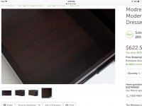
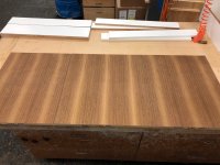
The 3 doors are Teak, here is a pic of them as they will be on the cabinet. If you look close you can see the joint between them;
Tomorrow I hope to make some good progress on assembly.
So a couple nights this week I went over to the cabinet shop. Laid up the veneers on 3/4” shop ply one night and this afternoon went over and made the rough cuts for the main outside cabinet and then the doors. This is my first time laying up plywood/veneer, way more work and harder than I thought, and this with all the right tools. The cabinet body is Wenge and when finished should look like this;

The 3 doors are Teak, here is a pic of them as they will be on the cabinet. If you look close you can see the joint between them;

Tomorrow I hope to make some good progress on assembly.
- Status
- This old topic is closed. If you want to reopen this topic, contact a moderator using the "Report Post" button.
- Home
- Amplifiers
- Pass Labs
- Aloha F5 v3 part 2, console build
