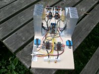
I haven’t had too much time and progress is slow, but this is what I have done since last time with my MoFo with a twist. I still need to mount the switch mode supplyes.
Very nice

Frank in your schematic wath is it "Q2" ?I don’t think so, unless you use a input transformer to separate the grounds since they will have to opposite polarization. See schmatics.
What advantages in this configuration did you want to get?I don’t think so, unless you use a input transformer to separate the grounds since they will have to opposite polarization. See schmatics.
There are no advantages in using a input transformer, this was an answer to your question.
Quote
“I have an existing chassis with a Firstwatt type power supply,+/- 23 volts.Would it be possible to run one channel off the + supply and use a complement p ch mosfet run off the - supply for the other channel? I know there are no IRFP250 complements out there (to my knowledge), maybe parallel IRFP240's and their complements? I know,I know---don't be a cheapskate,its just an idea.”
What is it about passive amplifier loading that sounds so nice (at least to my ears)? The MoFo has become my favorite amplifier now, it just sounds right, especially with my Markaudio Alpair 12P's in Super Pensils.
When I swapped out the switch mode PS for a linear PS and the bass just finally worked. The transformers are slightly undersized, about 80VA per channel. They're two Parts Express clearance toroids I've had sitting around forever.
Sagging PS voltage magic? Listening to some Chris Stapleton now and just wow!
I'm thinking of building my MoFo with a linear PS.. Does anyone have a circuit I can follow.. Thanks
My MoFo supply. Rectifiers, 30000uf, 0,120ohm, 30000uf. Per channel. 2,3 A bias and 23V.
No hiss, hum, etc.

I have an existing chassis with a Firstwatt type power supply,+/- 23 volts.Would it be possible to run one channel off the + supply and use a complement p ch mosfet run off the - supply for the other channel? I know there are no IRFP250 complements out there (to my knowledge), maybe parallel IRFP240's and their complements? I know,I know---don't be a cheapskate,its just an idea.
Just another thought,how about using lateral mosfets for the +/- supply idea.They can be bought as complements.The IRFP250 has no direct complement from what i've read so far and there are a lot of opinions on complements for the IRFP 240's.From what i've heard the mofo as it sits is very good,i'd hate to lose that but i guess you never know until you try.Anyone have thoughts on this idea?
Hi El ReinoMy MoFo supply. Rectifiers, 30000uf, 0,120ohm, 30000uf. Per channel. 2,3 A bias and 23V.
No hiss, hum, etc.
did you compare with smps?
The Universal v3 PSU + Gnd - board can be turned into two parallel Gnd + boards merely by not connecting the grounds together in the center of the PCB.
That's basically what mine is. 15VAC transformer that loads down to 12.6VAC for about 17.5VDC out at 1.3A bias. The only difference is I replaced the resistors between the cap banks with 2mH, 4A inductors.
I'll probably go with a 15VAC, 250 or 300VA when I build into chassis. Those little transformers mechanically buzz too much.
Sorry, I can’t help youHi El Reino
did you compare with smps?
")
The Universal v3 PSU + Gnd - board can be turned into two parallel Gnd + boards merely by not connecting the grounds together in the center of the PCB.
So are you saying instead of a + and - supply you can have 2 + supplies ?
If so, on the normal negative supply the r between the 2 sets of caps is in the negative leg of the circuit not the positive leg as in the positive supply.Would this have an effect on anything?
So are you saying instead of a + and - supply you can have 2 + supplies ?
If so, on the normal negative supply the r between the 2 sets of caps is in the negative leg of the circuit not the positive leg as in the positive supply.Would this have an effect on anything?
I would reverse the polarity on the caps of the negative side of the board (C1, C2, C5 and C6). Then reverse the connections of the negative side rectifier going to the negative side cap board:
V++2 to D--2
V+2 to D-2
V--2 to D++2
V-2 to D+2
Then go ahead and tie the grounds together of both sides for star grounding. This puts the resistors between caps on the + side of both sides now. Of course the V- output is now a V+
Yes,that is what i was thinking.
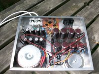
here's bodgy..
I dont have an active pre-amp so I've put an op-amp on the front with a gain of 3. It's 2sk1058 and hammond 159ZC. I'll start at about 1.1 amps bias cos I'm not sure of the heatsinks...
the power supply shown is from another project but I'll use half of it here for the op-amp. The fets will be powered from 2 x 24v smps that I had lying around.
Attachments
here's bodgy..
I dont have an active pre-amp so I've put an op-amp on the front with a gain of 3. It's 2sk1058 and hammond 159ZC. I'll start at about 1.1 amps bias cos I'm not sure of the heatsinks...
the power supply shown is from another project but I'll use half of it here for the op-amp. The fets will be powered from 2 x 24v smps that I had lying around.
Good job

- Home
- Amplifiers
- Pass Labs
- Build This MoFo!