Sure, here you go. Post 21 4P1L DHT Line Stage I´m using Colemans reg too
Last edited:
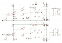
my simple voltage stage
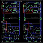
This is the complete schematic of the my voltage amplifier used also in the PF2019 including the power supply section allocated in the same pcb.
Mount the resistances in parallel configuration in opposite phase / direction.
R1,R2,R18,R19 100Kohm 1/2W 1% Mouser 594-MBB02070C1003FCT
R5,R6,R22,R23 220Kohm 1/2W 1% Mouser 594-MBB02070C2203FCT
R9,R10,R26,R27
R3,R4,R20,R21, 1000ohm 1/4W 1% Mouser 594-MBB02070C1001FC1
R11,R34
R7,R8,R24,R25 5600ohm 1/4W 1% <<< 5600ohm for 6072 and 4000ohm for the 12AX7
R15,R16,R31,E32 220ohm 1/4W 1%
R17,R33 3.3ohm 2W Mouser 660-MOSX2CT52R3R3J
R12,R30 470Kohm 1/4W 1%
R14,R29 150Kohm 3W
R13,R28 27Kohm 1W
C1.C3 220uF 6.3V OS-CON Mouser 667-6SEPC220M+TSS <<< not use for 12AX7
C2,C4 33uF 400V Mouser 647-UVY2G330MHD
C5,C6 100uF 400V Mouser 647-LGU2G101MELZ
CY1-CY8 10nF 440VAC RS 335-066 o 80-R474I210050A1K
U$3,U$6 IRF840 Mouser 844-IRF840APBF
U$11,U$7 33uF 400V Solen MKP
D1,D2,D3,D4,D6,D7,D8,D9 UF5406 Mouser 625-UF5408-E3
D5,D10 zener 10V 1W
KK1,KK4 Extruded Style Heatsink for TO-220 Mouser: 532-513102B25
Isolator Bergquist SP400-0.007-00-54 RS 169-2177
Isolatos TO220 nylon platstic Insulator hole size M3
The connections are 63862-1 (CUT STRIP) by TE Connectivity / AMP (cod. Mouser 571-63862-1-CT, cod. RS 718-7987)
The heat sinks have been grounded to avoid receiving radio frequency so these must be isolated from the transistor.
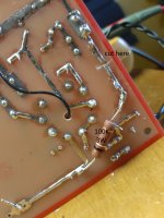
In order to keep the Vkf under the max value it is necessary add 4 resistors 2 x 100K 2W and 2 x 39K 1W (6072A) or 2 x 47K 1W (12AX7), see photos.
This is the complete schematic of the my voltage amplifier used also in the PF2019 including the power supply section allocated in the same pcb.
Mount the resistances in parallel configuration in opposite phase / direction.
R1,R2,R18,R19 100Kohm 1/2W 1% Mouser 594-MBB02070C1003FCT
R5,R6,R22,R23 220Kohm 1/2W 1% Mouser 594-MBB02070C2203FCT
R9,R10,R26,R27
R3,R4,R20,R21, 1000ohm 1/4W 1% Mouser 594-MBB02070C1001FC1
R11,R34
R7,R8,R24,R25 5600ohm 1/4W 1% <<< 5600ohm for 6072 and 4000ohm for the 12AX7
R15,R16,R31,E32 220ohm 1/4W 1%
R17,R33 3.3ohm 2W Mouser 660-MOSX2CT52R3R3J
R12,R30 470Kohm 1/4W 1%
R14,R29 150Kohm 3W
R13,R28 27Kohm 1W
C1.C3 220uF 6.3V OS-CON Mouser 667-6SEPC220M+TSS <<< not use for 12AX7
C2,C4 33uF 400V Mouser 647-UVY2G330MHD
C5,C6 100uF 400V Mouser 647-LGU2G101MELZ
CY1-CY8 10nF 440VAC RS 335-066 o 80-R474I210050A1K
U$3,U$6 IRF840 Mouser 844-IRF840APBF
U$11,U$7 33uF 400V Solen MKP
D1,D2,D3,D4,D6,D7,D8,D9 UF5406 Mouser 625-UF5408-E3
D5,D10 zener 10V 1W
KK1,KK4 Extruded Style Heatsink for TO-220 Mouser: 532-513102B25
Isolator Bergquist SP400-0.007-00-54 RS 169-2177
Isolatos TO220 nylon platstic Insulator hole size M3
The connections are 63862-1 (CUT STRIP) by TE Connectivity / AMP (cod. Mouser 571-63862-1-CT, cod. RS 718-7987)
The heat sinks have been grounded to avoid receiving radio frequency so these must be isolated from the transistor.
In order to keep the Vkf under the max value it is necessary add 4 resistors 2 x 100K 2W and 2 x 39K 1W (6072A) or 2 x 47K 1W (12AX7), see photos.
Attachments
Last edited:
power supply CLC vs SMPS
Yesterday evening a direct comparison between a power supply created with:
- toroidal transformer about 12.5V-0-12.5V
- diode IXYS DSA70C200HB Soft Recovery Schottky 200V 2 x 35A
- 10000uF 50V Nichicon KG
- Hammond 159ZJ
- 10000uF 50V Nichicon KG
and a HP 19.V 160W SMPS
The first problem is that it is not possible to use large capacitors at the output of the SMPS because this goes into short circuit protection so an SMPS should be created with this protection disabled.
So I have used only a 470uF 63V Nichicon Muse on the mosfet module.
In a direct comparison the timbre of the sound is identical but there is a greater naturalness and a better bass frequency in the version with traditional power supply (my friend speak about a + 5%) therefore in a system that accepts limits an SMPS can be used.
In the future I will create a custom SMPS to eliminate the limit on the output capactor.
Attachments
Last edited:
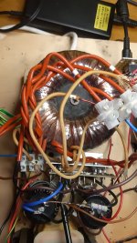
yes, a 0.1ohm 5W is enough to use the my HP SMPS with 10000uF.
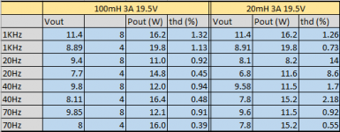
Here some data to compare a 100mH to 20mH so if you are not interested to a full range amp. from 70Hz also a 159ZE with 28mH 3A will be perfect.
Vin = 319mVrms for the 8ohm
Vin = 254mVrms for the 4ohm
Here some data to compare a 100mH to 20mH so if you are not interested to a full range amp. from 70Hz also a 159ZE with 28mH 3A will be perfect.
Vin = 319mVrms for the 8ohm
Vin = 254mVrms for the 4ohm
Attachments
Last edited:
CLC vs SMPS second test
Yesterday evening a direct comparison between a power supply created with:
- toroidal transformer about 12.5V-0-12.5V
- diode IXYS DSA70C200HB Soft Recovery Schottky 200V 2 x 35A
- 10000uF 50V Nichicon KG
- Hammond 159ZJ
- 10000uF 50V Nichicon KG
and
- HP 19.V 120W SMPS
- 0.1ohm 5W
- 10000uF Nichikon KG
power supply about 19.5V in both cases and bias 3A.
middle and high frequency are very similar and it is not easy to understand the differences
the low frequencies are very different, with the clc the bass is slow, soft and swollen the same bad effect that you get with many 300B while with the SMPS the bass are fast, dry and reach much lower.
How large is the main transformer? Do you think larger one would improve the sound?
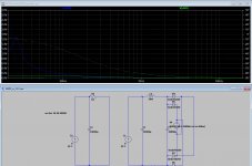
Here a fast simulation of the output impedanze of these power supply.
CLC give 0.5ohm at 40Hz and should be add the transf. secondary impedance
in both cases should be add the impedance of the output cap and mosfet.
Attachments
Last edited:
Yesterday evening a direct comparison between a power supply created with:
- toroidal transformer about 12.5V-0-12.5V
- diode IXYS DSA70C200HB Soft Recovery Schottky 200V 2 x 35A
- 10000uF 50V Nichicon KG
- Hammond 159ZJ
- 10000uF 50V Nichicon KG
and
- HP 19.V 120W SMPS
- 0.1ohm 5W
- 10000uF Nichikon KG
power supply about 19.5V in both cases and bias 3A.
middle and high frequency are very similar and it is not easy to understand the differences
the low frequencies are very different, with the clc the bass is slow, soft and swollen the same bad effect that you get with many 300B while with the SMPS the bass are fast, dry and reach much lower.
Hi
How are you getting 19.5Vdc from a 12.5-0-12.5 mains powered transformer? Also, is that transformer property sized ? VA please.
Thanks
Eric
")
Can we have a "class AB or class B power buffer
Sure, just take an F4 and lower the bias.
one query , little off topic,
Can we have a "class AB or class B power buffer (with less heat and more efficiency)" like we have "class A power buffer".
didn't found any examples for power buffers other than class A.
yes
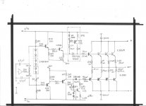
for example this design HP-REN-OS - Solid state Hi-end current amplifier by Bartolomeo Aloia with an innovative circuit to avoid the switching off of the transistors (here the simplified schematic)
but this is another thread so we shouldn't talk about it here
Attachments
Last edited:
Hi
How are you getting 19.5Vdc from a 12.5-0-12.5 mains powered transformer? Also, is that transformer property sized ? VA please.
Thanks
Eric
yes, the output voltage of both power supply SMPS and CLC are very similar 19V and 19.5V DC because the 200VA toroidal have more than nominal 12.5VAC with 3A bias.
In any case the semplified simulation show the limit of CLC on low frequency with 0.5ohm at 40Hz is obvious to hear a difference with 4ohm speakers.
The output capacitor will increase in both cases the output impedance on low frequency.
Last edited:
Question about
Hi folks.
I have a newbie question to ask.
I just finished one channel of the MoFo amp and set the bias without issue. I let it run for a while and re set the bias, checked the heat sink for temperature.
I then put it into my system.
Onkyo CD player that runs into a
Rolls Stereo Crossover ( Parts Express Rolls SX45 Stereo Two-Way Mini Crossover w/Sub Output )
into the MoFo and then into a
Audio Nirvana 10 inch full range driver.
AND the result was no sound output.
So my question is, do you think the Rolls Crossover provides enough gain for the MoFo?
Thanks for taking the time to consider this.
In the past I have assembled a couple of ACA's, an F5, and a Dynaco ST70
My knowledge and experience with power buffers is limited ( nil ) along with my knowledge of electronics.
My system presently runs an SE RH84 based tube amp running the Audio Nirvana 10 inch full range drivers and an F5 clone running the 15 inch Eminence 15 inch drivers.
The voltage gain of the Rolls Stereo Crossover probably is low but in any case you must have an output signal from Mofo.
Are you sure that the crossover settings are correct ?
no output from MoFo
Thanks for replying.
Yeah I did check the setting and even went back to my original setup to double check.
I took the MoFo back to the work bench and rechecked the bias, and found 0 volts.
Nothing appeared to be "smoked" so I replaced Q1, and re set the bias. Let it sit for several hours, re set it again.
Installed it into the system....and no output.
Re checked bias and it reads zero.
So either I have, made a mistake in assembly or the ROLLS unit is not a good match for this amp.
I guess I need to re evaluate and decide what direction to go.
O well.......
- Home
- Amplifiers
- Pass Labs
- Build This MoFo!