pictures of his car, too
")
 it would be nice to have it in my car also... at least I could use water radiating system to cool the mosfet
 Why on earth are you not connecting a load? Pretend it's a tube amp. This is a non-problem.
Out of curiosity, my PCB includes a bleeder on the output. Are you using one?
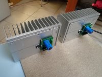
In fact, it might be better if you share some information about your build, perhaps even some pictures.
Yes, I know it's not normal to use the amp without a load. I simply found that it can happen for a mistake (as it happened to me) and also if it is for few seconds, it can cause same damage.
I'm using a custom PCB; I've just verified that the 1 kohm resistor is present between the output terminals, as reported on your schema. Maybe I could add a lower resistor (56 or 68 ohm / 5W for example) or simply protect the MoFo with a fast fuse...
Hi Zen,
I am testing amps, especially this one, with 8 ohm load almost at full power with square wave. Mofo style performs well. But I wonder, what is the power/voltage level with square wave. 2.83V or frequency ? 1KHZ, 5-10, or 20KHZ... ?
Which test condition must satisfy me ?
I have the obsession that at 20Khz with full load the amp must give perfect sq wave response.
Thanks.
Regards
Mehmet
@ Cpan
Sorry, I still haven't been able to recreate your problem. Heatsinking?
I don't think so, I can ordinary use (big) MoFo for quite a long time with this... and the problem with missing load arise immediately if I disconnect the speakers. I will recheck my circuit anyway, thanks a lot for your work 🙂
I see. So, you're running signal into them amp, then disconnecting the speakers?
Is this something you expect to happen often? If so, just fuse it.
What power supply are you using?
I use this procedure to reproduce the problem, but of course I don't expect it to happen often, hopefully. I discovered it with an error I made while I was measuring MoFo at the oscilloscope, so I was just wondering if there is a simple/elegant solution to avoid that *accidentally* disconnected load during ordinary operation could break my great MoFo 😅
BTW I'm using 2.5A@24V with Hammond 193V chokes. And I would anyway repeat that I find this amplifier simply Great both at measures and at listening!
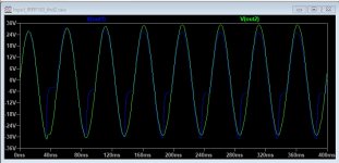
Today I went to check the performance degradation by reducing the inductance value in the simulation and I have seen that already with 50mH you can see some problems (here the sine plot at 20Hz)
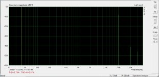
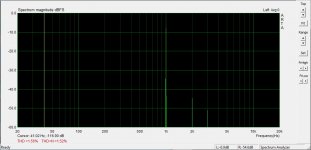
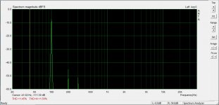
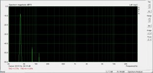
In the simulation of the output stage at 40Hz we have a thd of 0.7% instead of 0.1%.
Follows also the 4 measurements of the complete amplifier with 195T5 at 40Hz, 100Hz, 1KHz and 10KHz
In the simulation of the output stage at 40Hz we have a thd of 0.7% instead of 0.1%.
Follows also the 4 measurements of the complete amplifier with 195T5 at 40Hz, 100Hz, 1KHz and 10KHz
Attachments
Last edited:
Hi all, sorry if this has been asked before.... went through a few pages looking but didn't find anything.
Will Wayne's BA2018 linestage drive the MOFO? As it will be driving my horns I'll only be looking for a watt or two.
Cheers
Why use a linestage with feedback to drive a pure class A current amplifier ?
I think that the best solution is use vacuum tube for the voltage amplifier.
I can share files to produce my pcb with an integrated power supply.
It can be used with 12AX7 and 6072A.
Last edited:
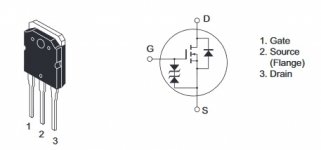
In the case of the IRFP150 in the datasheet is specified the max Vgs = +- 20V so I have used 2 x 15V 0.5W or 2 x 18V 0.5W zener like show in the image.
In some mosfet like the 2SK1058 these zener are integrated.
Attachments
Will Wayne's BA2018 linestage drive the MOFO? As it will be driving my horns I'll only be looking for a watt or two.
Cheers
I am driving big MoFo with a slightly modified version of the "bride of zen" by Nelson Pass (I simply bypassed the 10 uF output capacitance since MoFo has a 2,2 uF input cap is unuseful to duplicate, and I changed R108/R208 to 27 ohm in order drive big MoFo with 1 Vpp for full power out).
In this way I have a two-stage single-mosfet class-A single-ended zero-feedback system. Sound is stunning!
Claudio
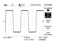
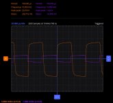
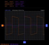
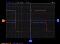
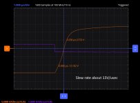
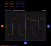
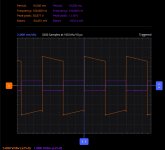
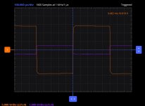
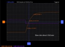
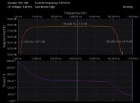
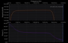
Hello I am here with new measurements using ADALM2000.
I don't see big differences from my PF2019 so therefore there are no negative effects using the inductance instead of the current generator on the source of the mosfet.
I don't know why the slew rate is low in both the amplifiers, Pathos declare value of 38V/usec here.
T.T.
I don't see big differences from my PF2019 so therefore there are no negative effects using the inductance instead of the current generator on the source of the mosfet.
I don't know why the slew rate is low in both the amplifiers, Pathos declare value of 38V/usec here.
T.T.
Attachments
-
 PF2019_Squareware10KHz.jpg116 KB · Views: 76
 -
 PF2019_Squarewave100Hz.jpg112.6 KB · Views: 90
 -
 PF2019_Squareware.jpg96.7 KB · Views: 93
 -
 PF2019_Slewrate.jpg93.7 KB · Views: 102
 -
 Inpol_Squarewave10KHz.jpg121.9 KB · Views: 462
 -
 Inpol_Squarewave100Hz.jpg115.8 KB · Views: 466
 -
 Input_Squarewave1KHz.jpg88.7 KB · Views: 455
 -
 Inpol_Slewrate.jpg101.5 KB · Views: 462
Last edited:
- Home
- Amplifiers
- Pass Labs
- Build This MoFo!