there is always detail in datasheet, saying how much voltage for gate going above source is needed to make BigBadaBoom ; that's usually in range of 20-ish Volts
use 9V1 , as you can see in plenty of Papa's schmts and you're good - bigger enough than working Ugs, while lower enough than Dodo voltage
practically , everything between 7V5-16V, what you have in drawer
use 9V1 , as you can see in plenty of Papa's schmts and you're good - bigger enough than working Ugs, while lower enough than Dodo voltage
practically , everything between 7V5-16V, what you have in drawer
there is always detail in datasheet, saying how much voltage for gate going above source is needed to make BigBadaBoom ; that's usually in range of 20-ish Volts
use 9V1 , as you can see in plenty of Papa's schmts and you're good - bigger enough than working Ugs, while lower enough than Dodo voltage
practically , everything between 7V5-16V, what you have in drawer
OK, I found 10V 1W and 10V 5W in my super-lab. Which you is better to use?
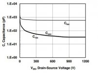
Yes, the capacity will be higher at 20-30V but if this follow this trend should not be a problem (here the plot of another model).
Here is the cap plot of the Semisouth SJEP120R100
Ciss also given at DS 1000V
Difficult to estimate the values at 20 Vds
Attachments
OK, I found 10V 1W and 10V 5W in my super-lab. Which you is better to use?
1W is enough
in fact , 0W5 are customary used there
Hi ZEN,
What about laterals for MOFO ?
Your comments please.
Regards
Mehmet
in source follower arrangement , I would always look first to use part with greater xconductance, after that looking at capacitances , and think of linearity in last place
ppl are looking for laterals thinking about better linearity in most cases, but here that's not so critical (follower thingy working in that manner that source is always trying hard to follow whichever way gate is traveling)
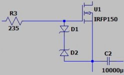
...should I use a 5W 20V gate-source zener .... or should I use some different value?
The MOSFET gate glass WILL blow-up at 40 Volts.
The datasheet says about "20V" to cover for bad days or careless users.
We NEVER need even 10V of gate drive.
Generally not even 5V, for post-1990 MOSFETs, in audio circuits (we do not need 50 Amps).
Power? What are you putting into the input jack? Few preamps can deliver over 0.1 Watts (8V in 600 Ohms). The Mofo wants more voltage but that often means less current. And the diode will only conduct half the time.
6.8V 0.5 Watts is a happy value. If you have a bag of 10V 1W, that's perfect also. (I would not want to use 5W: they leak more, and are more expensive for no benefit.)
Thanks a lot for your explanation! ")
I am using the IRFP250 as suggested in the original MoFo document and I am running it at 2,5A / 24V power supply (using Hammond 193V choke). I will try with the 10V 1W that I already have at home, then.
By the way, I am driving it with a slightly modified version of the Bride of Zen in order to have a max of "clean" 24Vpp to drive the mosfet...
Attachments
Regarding the turn-off glitch when yanking the DC jack (not recommended) we could also consider taming that with a resistor of perhaps 10 ohms or so across the inductor.
No. I'm sorry that's a dumb idea AC-wise. No idea where I was going with that. Disregard.

Overload when loudspeaker are disconnected?
I am building a pair of big MoFo. It sounds and measures great, but it happened that I had some signal @input while there was a missing load on the output and current absorbed rised over 10 amps. Is it normal? What should I do to avoid this behavior that may occur for a mistake?
I tried to add Gate-Source zener (10, 18 or 20 volt is the same) but it still happens that MoFo starts absorbing more than 10 amps if I drive it with a signal while load is disconnected. Any suggestion to avoid it? I am just thinking of a "fast fuse" on Vcc to immediately shut down MoFo if it starts absorbing more than 4-5 A. It is not a very elegant solution, I guess...
put fuse in DC line
and do not drive it without load , what's the use of it?
ever tried driving a car without wheels ?
solder 47-68R/3W across output terminals, if you insist in driving it without load
that way it'll see some load , without disturbing load line with speaker connected
and do not drive it without load , what's the use of it?
ever tried driving a car without wheels ?
solder 47-68R/3W across output terminals, if you insist in driving it without load
that way it'll see some load , without disturbing load line with speaker connected
Why on earth are you not connecting a load? Pretend it's a tube amp. This is a non-problem.
Out of curiosity, my PCB includes a bleeder on the output. Are you using one?
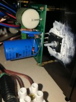
In fact, it might be better if you share some information about your build, perhaps even some pictures.
Out of curiosity, my PCB includes a bleeder on the output. Are you using one?
In fact, it might be better if you share some information about your build, perhaps even some pictures.
Last edited:
- Home
- Amplifiers
- Pass Labs
- Build This MoFo!