Originally Posted by Ralph G
......
My Title says "Balanced MoFo Zeus like".......
entirely possible..
Makes sense. So I could probably find usable results with a DMM and something like this: Online Tone Generator?
Measure across the RC network - from the Edcor output to ground?
not with DMM , Bubba
see how far they're good for AC measurements
functions of C1 other than blocking DC?
I was doing an experiment last night, thinking my preamp( the Chinese M7 clone) has the output cap already, I might as well just jump the C1 on the MoFo, to my surprise MoFo went silent, as soon as I remove the alligator clips that short the C1, it sang again. What gives?
I was doing an experiment last night, thinking my preamp( the Chinese M7 clone) has the output cap already, I might as well just jump the C1 on the MoFo, to my surprise MoFo went silent, as soon as I remove the alligator clips that short the C1, it sang again. What gives?
The components used for my new amp are: FQA48N20 as Mosfet. 2SK170 as input Jfets (I have quit a lot of these). The mentioned LL1539 are used as input transformers. And the output "chokes" are the salvaged 500 VA toroids (2 *40 VAC output used as choke). The resistance is around 0.15 ohm per secondary. And I'm running it at 1 amp per Mosfet (but you can run close to zero amps: this coupled choke runs nicely Class B). Max output is currently around 25 Watts at 8 ohm and 35 at 4 ohm (and even a bit more at 2 ohm). Output impedance (measured) is depending on the idle current. With the 1 amp it is around 0.7 ohm. The Mosfets are matched, so no need for a DC balancing (one channel has a DC offset of 7 mv, the other channel 2 mv).
After thinking, simulating, building, thinking, simulating and building, I came up with this amp. This version is working nicely. The bass is really good. More pressure compared to the original MoFo (lower damping or higher current?). The soundstage is big and there is absolutely no fatigue.
But: the original MoFo has a better "imaging". Every instrument has air around it. This is a really, really nice feature of this amp. Addicting. And there is more sparkle. I cannot measure this (the balanced version goes also really high). But the original MoFo is a bit brighter.
.........
Does anyone have some advice (or opinions)?
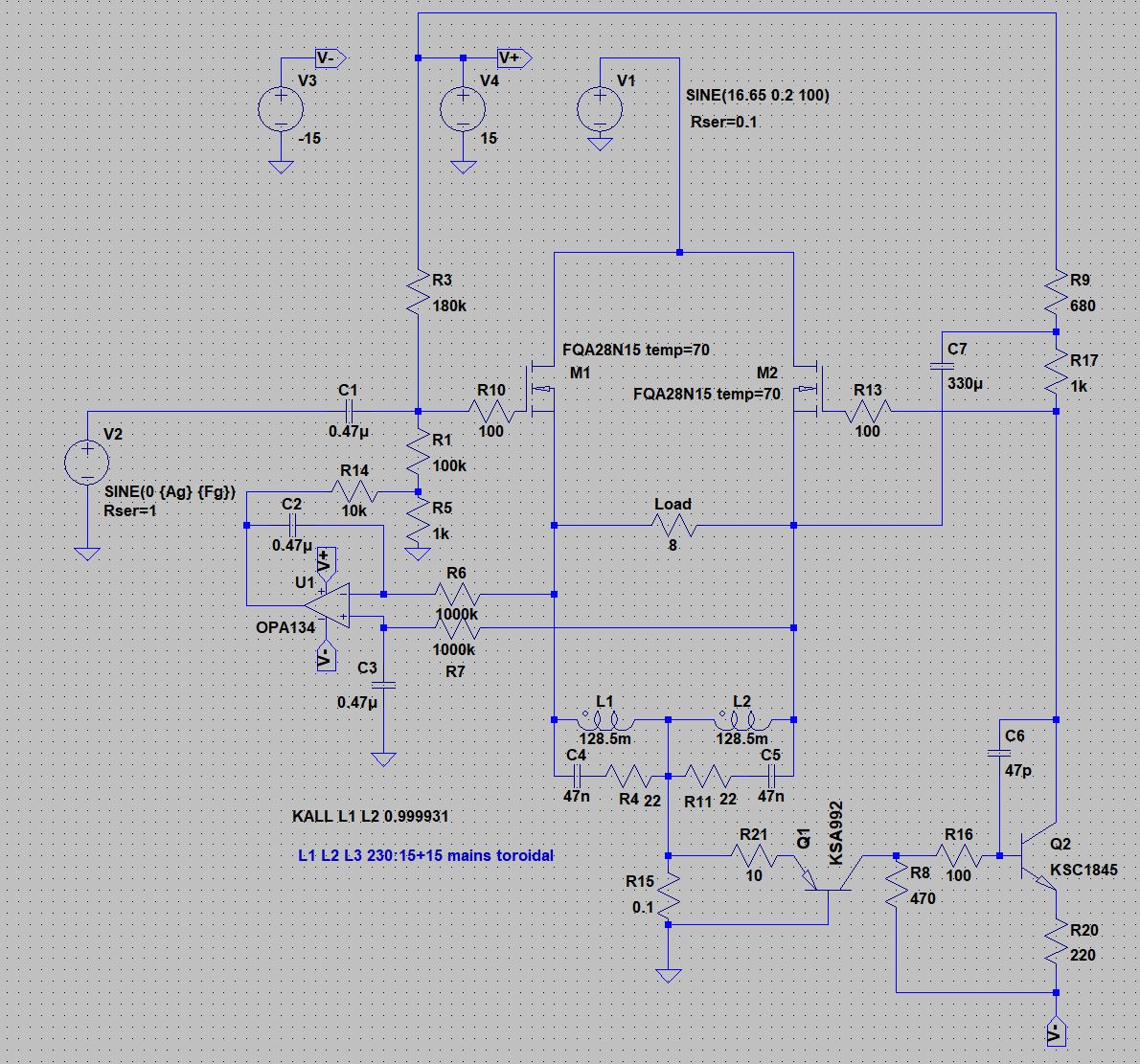
I have been thinking about a balanced version like that described by Ralph G, with the advantage of no output caps and being able to use the centre tapped secondary of a standard mains toroid for the inductors. But with a balanced version the distortion profile changes (even order harmonics tend to cancel) perhaps explaining Ralph G's comments above. I plan to try the following circuit. A CCS at the bottom (Q1) tries to keep the combined current of the two halves constant. The input signal drives the left hand side and the CCS drives the right hand side via Q2 with the help of bootstrapping. The distortion profile remains the same as the non balanced version with no cancelling of even order harmonics. I've added an offset servo that works to keep zero differential voltage across the load.
Obviously this is a strictly class A amp. The simulation works well, but I haven't built it yet. I plan to breadboard it sometime over the next few months after I've finished my current project.
Attachments
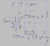
Obviously this is a strictly class A amp. The simulation works well, but I haven't built it yet. I plan to breadboard it sometime over the next few months after I've finished my current project.
My version works class B... I do use a lot of current, but it can run class B.
My buffer at the entrance of the amp (driving the Lundahl) is generating a bit of 2nd order harmonics.
But I think that running DC through this Lundahl is the reason for loosing a bit of "air". I'm looking at a nice 195T5. I can buy them cheap in Germany. The cap in the output of the original MoFo has way less impact on the sound than all the other parts I'm afraid.
welcome, so this is a learning experience, in another amp, you can probably get away, just so happened this one is not...
Definitely a good lesson, thanks again Tony.
Hi
where can you buy cheap 195T5 in Germany?
I live in Germany too
I don't live in Germany (but I live really close to the border and have to speak German every day
All Hammonds can be bought really cheap at btb (the tube seller).
75 euro for a T5. Not too bad.
Last edited:
@ btb-elektronik.de it costs 73€
@ mouser 89€
These things are heavy. I don't know if Mouser includes shipping for these. BTB also charges a lot for shipping to Holland. So I have to send them to a German contact.
The normal price for these 195T5 is way over 100 euro in Holland.
I have ordered a lot at BTB. Good company.
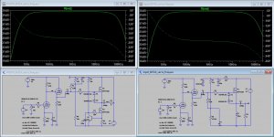
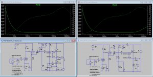
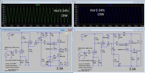
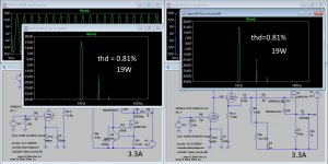
Here some simulations to compare my Power Follower to the MoFo / Inpol amplifier also using cheap choke with 50mH Rdc=0.7ohm.
The main problem could be the capacitance parasite of the inductance.
MoFo is very near to PF but more efficiency, half power supply voltage so less power to dissipate.
The main problem could be the capacitance parasite of the inductance.
MoFo is very near to PF but more efficiency, half power supply voltage so less power to dissipate.
Attachments
Syl20m,
Not really thinking much, I built my MoFo monoblocks with a 'wide' heatsink having what should have been plenty of thermal dissipation on paper, but since then my MoFos have stopped working twice. I built original MoFos, biased at 1A. I don't have an IR thermometer, so I don't know exactly what temperature they were at, but I am suspecting that the heat doesn't travel 'middle-to-sides' nearly as well as 'bottom-to-top'.
For my next MoFo , I will be looking to get sinks more like what you show, with a significant 'chimney effect'.
Having said that, it's possible my MoFos are failing for a completely different reason; perhaps the no-name power bricks I am now looking to replace.
Kind regards,
Drew
Last edited:
- Home
- Amplifiers
- Pass Labs
- Build This MoFo!