I am using my SIT 1s to drive JBL 2441s with the TRUEXTENT diaphragms.
The last couple of years have been in search of the best crossover arrangement.
I have been using the input and output caps of the SIT1 as part of my crossover. 0.32uf at the input and 25 uf at the output. These are placed near the loudspeakers for ease of changing the value. There is a 4/5 mH choke in parallel along with a shunt resistor to set level and 5 uF of capacitance to roll off the 2441s which make the blending with the FOSTEX T500s MUCH more homogeneous. The T500s input is taken from the junction of the 25 uF cap and the choke, followed by a cap and a choke giving what is a very slow slope fourth order. I can say the FOSTEX sound much better with as little lower frequencies directed toward them. I used to insert them at the amplifier's output.
Looking at measurements made with REW looks like I am getting a 3rd order crossover slope at the nominal 500 Hz.
I have been using Mr. Waslo's Xsim and have found there to be a good correlation between what I see there and what I measure but I am wondering what to do with the spec'ed 4 ohms of output impedance. I have tried using a four ohms resistor in series with the model which seems to improve my correlation but wonder if this is real or coincidence.
Xsim is a great tool, especially for those wanting to learn how crossovers work.
My question is how do you include the output impedance in the crossover model? Is the four ohms in series correct or should it be four ohms in parallel? From the model the four ohms in series really affects what happens down the line where the four ohms in series simply attenuates which makes me think that is not what is happening with output impedance.
Am I on the right track or is it impossible to use the output impedance within the Xsim model?
Any thoughts or counsel, please?
Last edited:
You can treat the SIT-1 as a voltage controlled voltage source in series with
at 4 ohm resistor at the output.
I am not familiar with Xsim, but you can use Spice (LTSpice or MicroCap etc.)
on this after you come up with a model for the loudspeaker driver.
Examples of modeling that from the impedance curve can be found in:
http://www.firstwatt.com/pdf/art_cs_amps.pdf
Or you can just plug parts in and measure the frequency response across
the driver terminals and/or the acoustic output.
THANKS for your note.
I assumed the 4 ohms in series was right since it correlated with what I was measuring but nothing beats being sure.
Being a master of SPICE would make XSim superfluous for you but for those of us on the mortal plain XSim is a great tool. In conjunction with REW you can see where you are going and make good predictions of what can happen.
I had read over that article (again) but still felt unsure.
I am going to sneak in another one. I am wanting no components in series with the driver so i am using only a shunt resistor to set level. All seems to be fine. The amps do not seem to run any hotter - but then they always run HOT.
Would you be concerned about me using a 3.8 ohms resistor in parallel with a (measured) 12 ohms impedance of the driver? Sure seems to sound better! I was using the carbon DUELUND resistors which did sound better than regular ones but there is no resistor like no resistor!
I have done plenty of plugging in parts in both the system and into Xsim. There is so much to be learned from just trying things! But it is still good getting guidance from someone who is a few lifetimes ahead.
THANKS,
Would you be concerned about me using a 3.8 ohms resistor in parallel with a (measured) 12 ohms impedance of the driver?
Nice thing about SIT-1 and 2 is you can short the output all day long if you like.
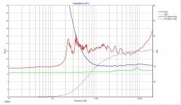
After more consideration I can see that trying to use the FOSTEX t500 and the 2441 in parallel unless I attenuate the drivers with more series resistance than I want to use I will never get much above 2 ohms from around 6 kHz on up. Below that it rises steadily to well over 100 ohms below cutoff.
I guess my question is - on an ideal basis - I figure it is better to have the impedance higher than this for sonic reasons?
Tonight I am going to try the drivers in series which brings the impedance up to a bit over 4 ohms in the same region.
The t500 measures a bit over 6 ohms for almost all of its range, not the 8 ohms their graph shows. There is a little blip where it rises slightly.
Would the amplifier sound better with less of a load?
Starting to think my idea of using an ACA for the Fostex might be more worthwhile than I originally thought! Need to put it together and find out but I cannot think that the ACA would sound better than the SIT even in this situation.
Any chance of a preview of the next SIT iteration?
Would the amplifier sound better with less of a load?
It will sound a little different. You are the one to decide if it is better.
ZM: I worry that might be the case though I would have no idea why!
I guess I am trying to find out what the amplifier would prefer or it the amplifier couldn't care less!
I assume the amp produces little power with that kind of a load and I do not need much power way up there! So that could be a wash.
Yes, it sounds just fine as it is but then I now see that I have presented this load to the amplifier pretty much since I got it so I have no basis of comparison.
So is there a "rule of thumb" (don't we wish DIY audio was chock full of these?) for an optimum load for the SIT amplifiers?
THANKS for all counsel,
I am talking about a series vs parallel crossover network!
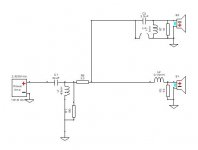
The network the SIT 1 sees starts with a typical second order high pass this will go to the 2441 and then to the T500 and then to ground. You use caps and inductors in parallel with the drivers to effect the frequency range of each - see Series vs. Parallel Crossover Networks Not the greatest article on this but the only one I can find quickly.
Very interesting how they interact. Will probably have to use some kind of resistor at the input of the amp to get the level down.
if executed correctly (each driver having own band ) , it is irrelevant which type of xover you're using (series or parallel)
amplifier will see just one driver in adequate frequency band
so , if JBL is (say) squawker while Fostex is tweeter , then everything is OK
why don't you post exact schematic ...... i have a slight feeling that you have values OK , while understanding of circuit is not so OK
amplifier will see just one driver in adequate frequency band
so , if JBL is (say) squawker while Fostex is tweeter , then everything is OK
why don't you post exact schematic ...... i have a slight feeling that you have values OK , while understanding of circuit is not so OK
some pictures.
Xsim by Bill Waslo is what I used.
If I place the FOSTEX input after the series resistor I get a higher impedance and a droopy response.
I will try both.
But this is where I am.
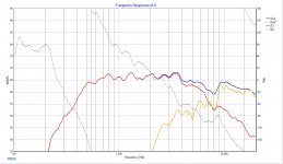
My frequency response is at my listening chair. Probably not how it is usually done but I figure I should include the room. If you would like to see the measurement files I will post them.
I should have included a REW room response with crossover but I forgot to bring it with me. Will post one tomorrow.
Xsim by Bill Waslo is what I used.
If I place the FOSTEX input after the series resistor I get a higher impedance and a droopy response.
I will try both.
But this is where I am.
My frequency response is at my listening chair. Probably not how it is usually done but I figure I should include the room. If you would like to see the measurement files I will post them.
I should have included a REW room response with crossover but I forgot to bring it with me. Will post one tomorrow.
Attachments
I know.
I reconfigured with series resistors to get the impedance up!
Just thought I would show you what I was doing since you asked.
any thoughts on who makes the best resistor for crossovers?
I have used the DUELUNDs but I have found much to my surprise the new thin films from ARCOL/OHMITE have very little sound to them and are MUCH cheaper.
I do think the DUELUNDs can be a little tizzy on top - of course my records are probably more than a little tizzy on top!
The mystery is the source of the entertainment.
Yes, I know that. Nothing about that bothers me.
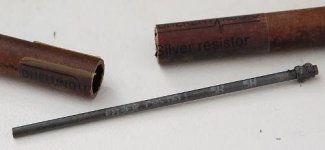
There is no question the DUELUNDs sound better than any other resistor I tried.
If I could make two equal resistors with the pencil leads I would do it myself!
A solid length of carbon has to be better than most of the resistor construction methods.
Someone on another thread had mentioned he thought thin film was the way to go. I saw these new resistors from OHMITE and though I would give them a try. I have been very pleased with the sound.
They should different and they have their own set of compromises (all rather small of course) but I think I like them better. Time will tell ...
I do not know if the pencil-lead is a joke?
However it makes some sense. Classic pencil "lead" is powdered carbon and clay. Classic "Carbon Composition" resistors were powdered carbon and clay. Carbon/clay mix gives different hardness (pencil) or resistance (resistors). I did not know the two products overlapped in recipe, but considering the *large* range of CC resistors (10r to 10Meg all the same shape/size) they must.
Carbon Comp resistors have a bad rap in audio. They tend to be hissy (even crackly) and drifty. This is because they are not "solid" but rather millions of carbon-carbon touch-contact points. A low-pressure contact is an untrustworthy contact. But the issue arises mainly for higher values in very low level circuits (preamps, not speakers). And also I believe because of the very-very-very low price the CC resistors commanded. Even Allen Bradly, who had good process, could not up-price the CC parts much because that might hurt sales of their premium wire and film resistors.
Good pencils command good price. Their buyers get very intimate with their "leads". I can believe Faber Castell makes a smoother tighter "lead" than the guts of old CC resistors.
The guy who wrote Walden, his family business was pencils. In the period after the "good graphite" from England ran out. The Thoreau family was among the pioneers of grinding *coal* down to super fine powder, and also worked on clay-mills, to get the perfect pencil point. In another project, Bell Tel used powdered coal in carbon microphones but after mass research decided that the best stuff came from ONE drift in one mine in Pennsylvania. So they bought the farm (leased exclusive rights to that branch of the mine to supply the needs of the whole Bell System).
Dry-cell batteries (even dead) can be busted open (carefully! wash-up after!!) to yield a carbon rod of good consistency. However the electrical resistance is very low, since it is a Power device. I dunno if you can get even a few Ohms from a pack of cells.
Mechanical pencils these days are not clay (too brittle in thin diameter) but carbon and a polymer. I recall trying to get an Ohms number and not getting consistent results.
You know DUELUNDs silver resistor are with Faber Castell pencil lead inside.
100 % verified by Diy folks
I wonder what the "silver" stands for...
- Status
- This old topic is closed. If you want to reopen this topic, contact a moderator using the "Report Post" button.
- Home
- Amplifiers
- Pass Labs
- SIT 1 and crossovers