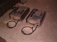
As requested close-ups of my amps.
Final Stats
Total Bias 11.8 amps @ 21.8V
Amount of Heat LOTS!!!!!!!!
IRF244 output fets. Sink Temp 58C Chip Temp ~105C
INYX DSEI30-06A Rectifiers operate @ 120C on chip
1 KW 21V VicMag Dual Secondary transformer
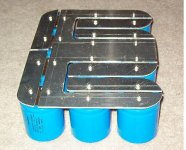
CRCRC Filter R=0.10ohm Total capacitance 432,000 uF equally distributed
ABS DC =+/- 100mV both channels
RelDC = 2mV on one channel and 32 mV on other.
20mA total diff pair bias. Using ZVP current source and precision voltage reference. Will up to 40mA bias at a later date.
AC Current Gain. Not Measured yet. Still breaking in caps. Used Panasonic FC type caps.
Sound is very good. Extremely dynamic with incredible control. Sound stage is precise. The impression I have is that each instrument is not only in 3d but there is space between instruments. In other words there is very little diffusion of the tonal characteristics of the independent instruments.
What I don't like is most likely my fault. The spectral balance seems to be a little bright. I think due to the IRFP244 that I used. Before the cart is put before the horse, this will be tamed somewhat when the AC current gain is finallized and the feedback cap is tuned. I am presently using 5pF which is most likely too small. (must play some more with it!!!!).
At present I am very happy with the capacity of the heat sinks. Initially they seemed too small but in reality they are holding the temperature very well. The pictures don't do justice to the size as the amp measure 18" by 24" by 8" tall.
Final Stats
Total Bias 11.8 amps @ 21.8V
Amount of Heat LOTS!!!!!!!!
IRF244 output fets. Sink Temp 58C Chip Temp ~105C
INYX DSEI30-06A Rectifiers operate @ 120C on chip
1 KW 21V VicMag Dual Secondary transformer
CRCRC Filter R=0.10ohm Total capacitance 432,000 uF equally distributed
ABS DC =+/- 100mV both channels
RelDC = 2mV on one channel and 32 mV on other.
20mA total diff pair bias. Using ZVP current source and precision voltage reference. Will up to 40mA bias at a later date.
AC Current Gain. Not Measured yet. Still breaking in caps. Used Panasonic FC type caps.
Sound is very good. Extremely dynamic with incredible control. Sound stage is precise. The impression I have is that each instrument is not only in 3d but there is space between instruments. In other words there is very little diffusion of the tonal characteristics of the independent instruments.
What I don't like is most likely my fault. The spectral balance seems to be a little bright. I think due to the IRFP244 that I used. Before the cart is put before the horse, this will be tamed somewhat when the AC current gain is finallized and the feedback cap is tuned. I am presently using 5pF which is most likely too small. (must play some more with it!!!!).
At present I am very happy with the capacity of the heat sinks. Initially they seemed too small but in reality they are holding the temperature very well. The pictures don't do justice to the size as the amp measure 18" by 24" by 8" tall.
Attachments
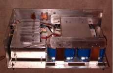
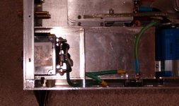
The 120VAC enters through an IEC filter. The switch is a 30 amp breaker. For protection I also used a fuse. In rush current is limite by two limiters in parallel. NOTE. I initially use sloblo fuses of 6 amps. These would hold for a while and then blow. After the econd time some magic smoke started to leak from the fuse holder. I am not sure if they were faulty fuses or if it was that they were operated too close to there max design but I ended up replacing the holder since the fuse and the holder had become one. Presently using a 10 amp quick blo. Steady current is 6.3 amps. I can blow th 10 amp if the PS is short circuited. (From Experience!!)
Attachments
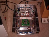
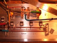
This is the gain fets on one side. The CCS are to the left just out of the picture. The buss for the Rails and output are 4 awg solid copper. These are held in place by .5inch Lexan blocks which mount to the backplate. The gate buss is 12awg solid copper. Wish I had silver but oh well is wish I had alot of things. You can also see the current sense resitors and ground resistor on the top. These wouldn't fit on the cuircuit board so I made a seperate buss plate to hold them and mounted them to the back plate. All the wire used to carry power is 4awg silver plated OF Copper. I went to a high end auto stereo shop and was allowed to have their scraps. Not a bad deal.
Attachments
What beautiful work. Are you available for adoption?
The sound you describe is not likely the IRFP244. I am more
inclined to suspect that either the gain of the Aleph current
source is higher than you want, and/or the compensation
Collector - Base of the NPN transistor controlling the source
might be too low.
I assume you are driving them balanced.
Also, remember to load the outputs to ground - This is very
important on X amps - they dislike high common-mode open
loop gain. Usually 47 to 100 ohm on each side is enough.
np
Ground Resistorsand sound.
Nelson
Thanks for the reply and compliment. The Ground loading is 33.5ohms. I am not sure yet what the AC gain is but will measure it sometime next week. I want everything to break in more before I set some of those values. I also want to get the rel DC offset on the one amp down some more. (not because it is neccessary but because I can). I'll do some more research to understand your last comment better. At present, the voltage accross the source resistors is around .58V.
Scott
P.S. If you talked to my wife she may put me up for adoption.
!!!
A true 'Class A' (in both ways) project. I'm glad the sinks turned out to work well. I'll have to say, I've been impressed with all of your projects, but this one has a level of creativity, detail and overall cleanliness that few often achieve.
I hope you take those on the road this year in the fall so I can hear them!
Sandy.
")
Nelson Pass said:
What beautiful work... remember to load the outputs to ground... 47 to 100 ohm on each side is enough.
Dear Mr Pass
I would like to compare them with two mechanical springs trying to maintain the same distance from the center to the two relative points. Reasonable comparison?
JH
- Status
- This old topic is closed. If you want to reopen this topic, contact a moderator using the "Report Post" button.
- Home
- Amplifiers
- Pass Labs
- AlephX-100 Monoblocks