I wanted to let F6 builders know about my experimentation with some alternate parts. I started by building a stock 2-channel F6 using the recommended DIY schematic parts, including the Jensen JT-123-FLPCH transformers and matched LSJ74/LSK170 pairs for the input buffers. Power supply was the Pass recommended design. Power transformer was an AnTek AS-3218 300 watt toroid. At first I was dissapointed with the sound but after I got the bias up to 0.575 volts and let it burn in a few days, the results were shockingly good. So I decided, how cheap can I build this, and what will it sound like? I built a second 2-channel amplifier using the Triad TY-250P input transformer ($6 part!) some 2N5457/2N5460 A-grade pairs I matched myself (less than $1 each) and a pair of Chinese 8 amp 24VDC circuit board style regulated power supplies ($14 each).
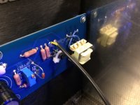
The result? Damn close. The original has the faintest edge in clarity, which I would venture is a combination of lower distortion and better phase linearity. The budget version is still better than any bipolar, mosfet or tube amplifier I have listened to, regardless of circuit topology. The big surprise was that the measured voltage gain remained the same with the TY-250P transformer, given that it is specified with a non-configurable center tapped primary that would theoretically yield a 2:1 ratio in this circuit. Still scratching my head over that one. The secondary pins will fit directly in the DIY circuit board while the primary needs jumpers that reverse the polarity for the circuit board layout. Transformer sits at an angle since the core is not the same footprint as the Jensen (see photo). Although if you are going for cheap, building this amp on a turret board layout or even a perf board is a no brainer. I especially like turret board because you can simulate double sided thru-hole design using the hollow turrets for underside jumper connections.
I can't really recommend the cheap regulated power supplies. Their heat sinks run 5 - 10 degrees C hotter than the output heat sinks! Spend the extra 50 bucks for parts and the time to build the recommended supply. I used passive output heat sinking on both versions and no doubt, a fan cooled system would yield even greater savings. I used a DIY store chassis for the stock version and built my own chassis using DIY store heat sinks for the budget version. Overall savings was a bit over $200 for the budget version.
This amplifier could be built for very little money if you build your own boards, can tolerate forced air cooling and downgrade the power supply to a 200 watt version. One last FYI, the bias zeners had to be upped to 5.6 volts to get either the stock or the budget version to bias properly.
Attachments
Nice work. It's almost blasphemy around here to say, gasp, you used a SMPS on your F6? I tried a pair of cheap 24v 5amp SMPS external bricks (used for LED lighting) on my M2 and it measured way cleaner than the 400VA linear trafo based setup with 8x30mF caps.
Thanks for showing TY-250P works.
Can you make measuremts to show difference between the two?
Thanks for showing TY-250P works.
Can you make measuremts to show difference between the two?
So far just a quick look on the scope at 1KHz sine wave with unloaded outputs. 1.0V input = 6.3V out and 2.86V in = 18V out. I got the same readings for each version of the amplifier. I intend to go back and take some measurements at 20Hz and 20KHz with an 8 ohm resistive load. Waveform looks clean at 1KHz. Will have to take a look at the extreems and also compare clipping into a load.
I do not own any test equipment that would allow me to make distortion measurements.
I do not own any test equipment that would allow me to make distortion measurements.
Ran some more tests. First off, a word of warning. Reversing the primary side polarity of the input transformer from what is shown in the schematic causes the amplifier to produce a fully clipped (48 volt) 20 Hz sine wave on the output (I was seeing if I could bridge two channels). Very bad. Amp has been stable with normal input polarity.
I hooked up a channel to a 6.6 ohm 100 watt wire wound load resistor and measured the following:
2.76V p-p sine wave in = 12.8V p-p out at all audio frequencies 10 Hz to 50KHz and beyond. No distortion was visible.
A rough look at phase shift using the XY display function on my dual trace scope shows the ellipse breaking open below 22.5 Hz, a few degrees of shift between 10 Hz and 100 Hz, no shift from 100 Hz to 1 KHz, then a slow shift with increase in frequency reaching 45 degrees at 14 KHz and 90 degrees at 28 KHz.
yup
care to share Triad datasheet?
attached
Attachments
triad will have 6db loss , comparing to original xformer in F6 , simply because you can't un-series primaries and connect them in parallel
input buffer with J113/J176 ...... I would go with non-complementary buffer , using 3 paralleled J1113 up and 3 paralleled J113 down ( as CCS) , trimpot in CCS sources and trimpot in upper sources , to fine tune DC offset on output of buffer ...... or primaries connected to buffer output via capacitor
also , judging by Triad graphs , some RC secondary loading would be necessary .......
practically ....... easy work if one is having decent scope and gene ......... not so easy if not
do you advise the non-complementary buffer for j113 and for the 2N5457 too?
or complementary 2N5457/2N5460 would have a decent performance?
Aren't 2N5457/2N5460 similar to J113/J176 ?
whatever you have , just try it and if your ears are happy ......
can't say for 2N vs. J - I don't have xconductance data for J
in any case , I would go with those having greater xconductance numbers , resulting in more cojones
and , you can always parallel them for each position , if you have quantity to choose from
- Status
- This old topic is closed. If you want to reopen this topic, contact a moderator using the "Report Post" button.
- Home
- Amplifiers
- Pass Labs
- F6 build options