Hi, I've been trying to find a good transistor set, for old Pass's design, http://www.firstwatt.com/pdf/art_classa_20.pdf.
And I've gotten somewhere with it in my simulation but it seems that my configuration is either doesn't have proper substitute transistors, there could be a design flaw or unreliable simulation setting.
I could use some help getting further with the design but I'm stuck figuring out where to go next.
MPSL01 = 2N5550
RCA1A16, RCA1A15 = MJE15030G, MJE15031G
2N5877 = 2N6341G
PS.
If anyone knows where to get 2n5877 SPICE model somewhere that would be great, but at the moment I don't know how to make one for it my self.
TinyUpload.com - best file hosting solution, with no limits, totaly free
Unfortunately its in multisim file. I should probably use other simulation tool than multisim? Or is it just a preference.
Unfortunately its in multisim file. I should probably use other simulation tool than multisim? Or is it just a preference.
What is it doing, not doing?
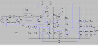
The plan is straightforward. For simulation, the exact transistors are probably not critical. It sure should come to a DC solution even if the huge POWER transistors are faked with tiny 2N2222. (My sim does not complain when I put 50 Watts in a quarter-Watt part...)
The plan is straightforward. For simulation, the exact transistors are probably not critical. It sure should come to a DC solution even if the huge POWER transistors are faked with tiny 2N2222. (My sim does not complain when I put 50 Watts in a quarter-Watt part...)
Attachments
Bob Cordells excellent book 'Designing Audio Power Amplifiers' has several chapters devoted to LTSpice and there is a detailed description on creating basic spice models.
This (attached) list of Bobs own models will cover 95% of generic audio circuits such as yours. The MJL21194/3C complementary pair seem suitable candidates.
Also search for Ian Hegglun's excellent lateral FET models.
This (attached) list of Bobs own models will cover 95% of generic audio circuits such as yours. The MJL21194/3C complementary pair seem suitable candidates.
Also search for Ian Hegglun's excellent lateral FET models.
Attachments
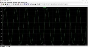
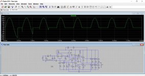
Well, technically doing fine and dandy but after Q5 the signal is incoherent mess.
I've been trying using
Q4 is a MJE15031G and Q5,6,7 MJE15030G.
If these don't lead me forward I'm checking next
D44H11 / D45H11.
So I'm not stuck on getting the signal to pass from the OPamp to end-stage to be finally amped up.
I've been trying using
Q4 is a MJE15031G and Q5,6,7 MJE15030G.
If these don't lead me forward I'm checking next
D44H11 / D45H11.
So I'm not stuck on getting the signal to pass from the OPamp to end-stage to be finally amped up.
but after Q5 the signal is incoherent mess.
And this relates to a simulation of the circuit in post #6 that PRR posted ?
I'm guessing it should work on 14... I'll try it. I just made an educated guess without reading Nelsons work.
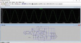
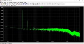
Its fine") May as well show some of the other gory details FFT and distortion at 2.83vrms output (1W/8ohm)
May as well show some of the other gory details FFT and distortion at 2.83vrms output (1W/8ohm)
Its fine
May as well show some of the other gory details FFT and distortion at 2.83vrms output (1W/8ohm)Attachments
I'm just reading Nelsons write up on this and that shows a 14-0-14 volt transformer which would actually give around -/+20 volts dc if we ran it at near to its continuous VA output rating.
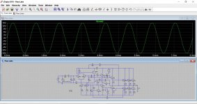
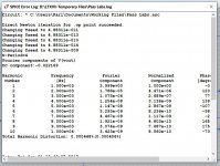
I've set the preset as per the instruction and that gives a current of just over 800ma in each output pair. Driver current is nearly 500ma giving around 10 watts dissipation in the little drivers but hey, this is LTspice with the indestructible transistors.
This is where using more suitable (hi beta) devices for drivers and outputs would pay dividends.
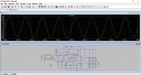
Also the bias preset is incredible critical in simulation. This shows the result of going from 1k45 to 1k47. I wonder if the real build is as critical and behaves like this ?
I've set the preset as per the instruction and that gives a current of just over 800ma in each output pair. Driver current is nearly 500ma giving around 10 watts dissipation in the little drivers
but hey, this is LTspice with the indestructible transistors.This is where using more suitable (hi beta) devices for drivers and outputs would pay dividends.
Also the bias preset is incredible critical in simulation. This shows the result of going from 1k45 to 1k47. I wonder if the real build is as critical and behaves like this ?
Attachments
Try it for current as well
15 volts, 8 ohms is approx. 1.9 amps peak. Multiply by 1.25 and we get 2.375 amps.
Bias current adjusted as per Nelsons method worked out at a shade under 800ma per pair. So 3 pairs equals 2.4 amps.
Near enough for Jazz
15 volts peak into 4 ohms is around 3.8 amps peak. Bias now 1.42 amp per pair.
So 3.8*1.25 is 4.75 and 1.42 * 3 is 4.26.
Its sort of in the right ball park.
- Status
- This old topic is closed. If you want to reopen this topic, contact a moderator using the "Report Post" button.
- Home
- Amplifiers
- Pass Labs
- A-class amplifier simulation