Hi Karen,
It seems that I not only have the problem with the finding IRF 244 transistors.
e-Mail link that you posted don't work.
I tried several times, but every time It was returned to me.
But, here it is:
Hello,
Thank you for reply on my question on the diy forum.
I would like to build Aleph 5 Amplifier, but I have problem with finding IRF 244 transistors.
Is there some similar devices that will work for IRF 244 substitution ?
What about IRFP 250 - I can buy them in my local shop, but a friend of mine told me that amplifier would have much more distortion with this device, is this true ?
How much higher distortion will be, compared to IRF 244 ?
Thanks for your time,
Strobo
>
>
>This Message was undeliverable due to the following reason:
>
>Each of the following recipients was rejected by a remote mail >server.
>The reasons given by the server are included to help you >determine why
>each recipient was rejected.
>
> Recipient: <help@passlabs.com>
> Reason: 5.1.1 <help@passlabs.com>... User unknown
>
>
Thanks Harvardian,
I allready ordered 50 x IRFP 240.
It seems that a many peoples used IRFP 240 instead IRF 244, and they didn't have any objections, so I will try the same way.
Is 50 pcs will do for 24 mached devices, or should I order more ?
How accurate they should be matched ?
---
Strobo
I allready ordered 50 x IRFP 240.
It seems that a many peoples used IRFP 240 instead IRF 244, and they didn't have any objections, so I will try the same way.
Is 50 pcs will do for 24 mached devices, or should I order more ?
How accurate they should be matched ?
---
Strobo
Hello,
For high heat dissipation I would recommend you to use mica type isolators with the silicon thermal paste.
They are a little more messy, but I think that they are better than
rubber type.
If using the silicon rubber type, you must not overtight the devices
with the screws, as the isolator will start to distort.
Regards,
Kristijan Kljucaric
The Aleph LED
The LED is there to show that the amp is powered up. It is most likely connected to the amp output since ground does not connect
to the PCB that it is mounted on directly. It would have required
another wire from the Main PCB to the output PCB to connect the LED to ground. Nelson saved a wiire and two solder joints and made the trace routing a little simpler by not having to bring ground to the output PCB. It will not affect the operation of the circiut being wired in this manner. Another great audio mystery solved. (Reply to question on first page of thread)
H.H.
Banned
Joined 2002
Hello JasonL,
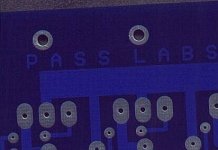
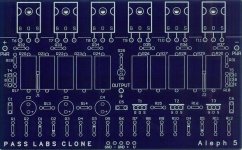
The all PCBs that can be found at http://web.vip.hr/pcb-design.vip , are made of FR-4 fiberglass material with Cu-50 mikron + Pb track overlay (tinplated), laser drilled, with two sided blue soldermask (instead of green), and with white component overlay, like it is showed on the next photos.
Regards,
Kristijan Kljucaric
Attachments
Banned
Joined 2002
DUDe
THOSE are some nice boards i see that you have taken your time to get them designed properly and nicly layed out.. i will be perchasing some i just have to wait till i sell my yamaha amp as i pormmised in my email i will be getting the pre-amp and 2 x aleph 5 boards.. no one still hasnt answered my question about cooling.. Can i use a fan to keep the heatsinks cool i dont know if my heat sinks will be good for my aleph 5 but i believe they willl if you need a pic ill post it or email it to you ..
( kristijan-k )
Thanks jason
Banned
Joined 2002
- Status
- This old topic is closed. If you want to reopen this topic, contact a moderator using the "Report Post" button.
- Home
- Amplifiers
- Pass Labs
- Pcb For Aleph 5