I found a giant chunk of heatsink at my local scrap dealer. It measures 9.75" wide, 2.25" high and 72" long. The base plate is 1/4" thick.
I'm interested in building a two-channel Aleph X amp. I'd like to build it as one component rather than as two monoblocks. I really like the Pass XA200 form factor chassis (rack width and about a foot high. I was thinking about cutting the heatsink into two 9.75" x 36" heatsinks.
The problem I see with this is that the fins would be running horizontally. It's been a while since my Thermo classes, but it seems that they'll be less efficient than if the fins were horizontal since the convective flow won't pull cool air across the fins. It seems to be a waste to cut this into a bunch of small pieces, and I really like the sleek look of having the fins running horizontally.
Does anyone have suggestions about the best usage for this material? I'm interested in building the largest stereo amp I can with the heatsink material I have.
Should I use it with the fins horizontally? Or would I be waaay better off to cut it into a bunch of 12" high sections and turn the fins vertically? Or just sell it and buy some stock similar to the stuff that Nelson uses on the XA200s?
Thanks in advance for your help,
Bryan A. Thompson
batee@roadslessphotographed.com
An externally hosted image should be here but it was not working when we last tested it.
An externally hosted image should be here but it was not working when we last tested it.
I'm interested in building a two-channel Aleph X amp. I'd like to build it as one component rather than as two monoblocks. I really like the Pass XA200 form factor chassis (rack width and about a foot high. I was thinking about cutting the heatsink into two 9.75" x 36" heatsinks.
The problem I see with this is that the fins would be running horizontally. It's been a while since my Thermo classes, but it seems that they'll be less efficient than if the fins were horizontal since the convective flow won't pull cool air across the fins. It seems to be a waste to cut this into a bunch of small pieces, and I really like the sleek look of having the fins running horizontally.
Does anyone have suggestions about the best usage for this material? I'm interested in building the largest stereo amp I can with the heatsink material I have.
Should I use it with the fins horizontally? Or would I be waaay better off to cut it into a bunch of 12" high sections and turn the fins vertically? Or just sell it and buy some stock similar to the stuff that Nelson uses on the XA200s?
Thanks in advance for your help,
Bryan A. Thompson
batee@roadslessphotographed.com
I would suggest cutting it into smaller lengths and using it with the fins vertically. You do say that you want to build the largest amp you can and it is indeed more efficient from a heat transfer standpoint with the fins running vertically.
Some time ago, I spent quite a while trying to come to conclusions about what size heat sinks are required for a given dissipation. I took a look at lots of results reported on the forum, and also built a mock-up of a single channel Zen IV. When I measured temperatures, it confirmed my estimates.
I found that starting at room temperature you can dissipate about 1W per 10in^2 of heatsink area while ending up with the heatsinks at about 50C. (that's about a 25-30 degree rise) That's of course with the fins vertical. And, Aleph or Aleph X circuits dissipate about 3x the rated power output.
So, I'd say you've got 2.25 in. x 2 sides per fin x 20 fins = 90 in^2 per inch of length, plus a little safety factor from the contribution of one side of the baseplate.
Multiply by 72 in. long and you've got 6480 in^2.
That should be good to dissipate 600+ watts of power, or enough to get you 200 watts RMS of amplifier power.
If you dice it into 6 sections, you'll get one big amp when you're done. I'd cut one side of the protruding backplate off so that when you butt the sections up against each other, the fins are all equally spaced rather than having a visible gap where the sections meet.
Keep in mind... these are MY conclusions, and consider what you paid for this advice.")
I suggest that you do some homework to make it your own and to avoid dissapointment. It's part of the fun
Some time ago, I spent quite a while trying to come to conclusions about what size heat sinks are required for a given dissipation. I took a look at lots of results reported on the forum, and also built a mock-up of a single channel Zen IV. When I measured temperatures, it confirmed my estimates.
I found that starting at room temperature you can dissipate about 1W per 10in^2 of heatsink area while ending up with the heatsinks at about 50C. (that's about a 25-30 degree rise) That's of course with the fins vertical. And, Aleph or Aleph X circuits dissipate about 3x the rated power output.
So, I'd say you've got 2.25 in. x 2 sides per fin x 20 fins = 90 in^2 per inch of length, plus a little safety factor from the contribution of one side of the baseplate.
Multiply by 72 in. long and you've got 6480 in^2.
That should be good to dissipate 600+ watts of power, or enough to get you 200 watts RMS of amplifier power.
If you dice it into 6 sections, you'll get one big amp when you're done. I'd cut one side of the protruding backplate off so that when you butt the sections up against each other, the fins are all equally spaced rather than having a visible gap where the sections meet.
Keep in mind... these are MY conclusions, and consider what you paid for this advice.
I suggest that you do some homework to make it your own and to avoid dissapointment. It's part of the fun
I have attached a link below that will take you to an extrusion very close to the one you have. I have assumed you want to build one Stereo chassis, this would give you 36" per channel.
If you cut the 72" length into 6 equal sections turn them 90 Deg and clamp them together mechanically you will have 2 Heat sinks approximately 12" x 27".
This configuration would offer you the greatest convection flow with the fins running vertically. Based on the C/W you should be able to dissapate 240 watts per side at 30 Deg C. rise above ambient.
http://www.thermaflo.com/bin/exdata...36&LengthUnits=in&SearchButton1=Change+Length
Regards
Anthony
Cut it up
Hi,
I would definitely cut it into 4 pcs or more, making it lower and wider, placing the sections side by side.
My experience is that doubling the height of a sink will only give you approximately 30% - or so - more energy dissapation capability(again, remember what you paid for the advice, as a kind fellow stated).
Keep in mind, that air has a fairly low thermal capacity. It heats up fairly quickly when rising through the "channel" between two fins of the heat sink, and therefore you'll reach a point where you just have warm air running along the heat sink without heat energy reansfer from metal to air. We don't want that. Contrary, we want a LOT of shorter air-"channels", in stead of few long channels. Make it low and wide, in stead of tall and narrow.
Jennice
Heatsink Calcs
In my research for which power AlephX to build. ie one my other half would let into the lounge! I came across the following site.
http://www.aavidthermalloy.com/products/euro_extrude/index.shtml
Looking at the European standard extrusion catalogue you should find an appropriate match and using the correction factors listed the simple maths will give you the overall C/W.
I found it easier to use and more detailed than the Thermaflo site Coulomb refers to.
Simon
Consensus seems to be function over form. Dang.
The above suggestions yielded the following results:
My ambient room temp is 22-25C. I found nothing at the Aavid site as far as a close match for my sink. Coulomb found something close, but with slightly shorter fins, at the Thermaflo site. Looks like a 35C increase will dissipate 320Watts (per channel), for a thermal resistance of ~0.11C/W. This matches the numbers provided by vpharris, so I'm inclined to believe the calculations.
Assuming I cut it into six sections (three for each channel), what would be the best way to distribute the heat generated by one channel over the three sections?
I was thinking of building a chassis out of 1/2" - 3/4" aluminum bar stock, then covering the top and bottom with vented aluminum plate and the front and back with solid aluminum plate, and just bolting the heatsinks to the bar stock to form the cabinet sides.
Is it possible to arrange the FETs for each channel so that they're on the different pieces? Or should I use some sort of a backing plate across the backs of the three plates, or are the large bars enough? If a backing plate, how thick?
Marqura,
If you like your theory, enjoy... I prefer my audio gear to survive.
Point is, that I have made some tests myself, which tend to give results not too far from the data sheets for the industrial heat sinks I've tried.
they come in up to 1 meter length, and their data sheet shows almost no improvement in heat sinking capability over the last 50 cm. It's not a linear function of height... theory or not ;-)
Jennice
Jennice said:Marqura,
If you like your theory, enjoy... I prefer my audio gear to survive.
Point is, that I have made some tests myself, which tend to give results not too far from the data sheets for the industrial heat sinks I've tried.
they come in up to 1 meter length, and their data sheet shows almost no improvement in heat sinking capability over the last 50 cm. It's not a linear function of height... theory or not ;-)
Jennice
Seems a little Harsh Jennice!!!

I think your plan for the chassis is fine, and practical.
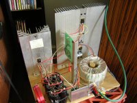
You can distribute the FET's across the heatsinks. Assuming that you have 12 per channel, then you get 4 per heatsink piece. If you are going to have the pieces 12 in. high, then you might be best with two rows of 2 on each piece. Spread them out so that each is using the same area on each heatsink. Like, 4 quadrants with one in the middle of each.
Can you put them all on one plate that spans the heatsinks? Yes, but no matter what, you'll lose some efficiency. That said, when I made my Zen IV, I was bound and determined to do it the true DIY way, with 'found' heatsinks (free from a local electronics recycler). They were too small and I bolted two together. Used a strip of Al where they overlapped, and coated the joint with heatsink compound. I later measured temperature right at the back side of the joint, opposite the FETs and compared that to an inch away from the joint and saw very little temperature drop, so I think it worked quite well.
If you choose to use a backer, probably 3/16 or 1/4 in. thick is good enough. If you have it screwed to the heatsinks securely enough (read: lots of screws) then the effect will be as though there is only one heatsink. I think the surface area of the connection is key. I'd probably want it to be at least 3 in. wide for something as big as you're considering.
Here's what that looked like on the mockup, with details to follow:
Attachments
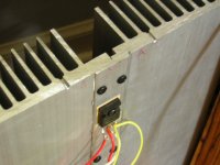
Here is what I did with a 48" piece of a similar Heat Sink.
http://wingzero.ath.cx/jleaman/gallery/album25/DSC00149
Here is a link to my Metal Work Album
http://wingzero.ath.cx/jleaman/gallery/album25
Regards
Anthony
http://wingzero.ath.cx/jleaman/gallery/album25/DSC00149
Here is a link to my Metal Work Album
http://wingzero.ath.cx/jleaman/gallery/album25
Regards
Anthony
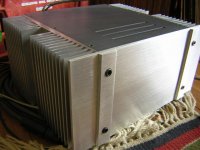
Wow Vince, That's a truely beautiful case.
But back to the original questions, T truely get the most of your sinks, I would go with 2 smaller monoblocks cutting it to 8 peices 8.5" tall with 2 sinks per side as you suggested. Use turrret terminals to support buss wires and connect the fets.
But back to the original questions, T truely get the most of your sinks, I would go with 2 smaller monoblocks cutting it to 8 peices 8.5" tall with 2 sinks per side as you suggested. Use turrret terminals to support buss wires and connect the fets.
Not meant to be harsh...
Coulomb: It wasn't the intention to be directly harsh.
Batee and others...:
It just tend to have a problem with people claiming to know better than the manufacturers of heat sinks. Maybe he should get a job there. One thing he forgot to take into account is that thre air speed can't increase (unless it means that more fresh air is drawn into the circulation). The new air is also heated up, which is - again - dependent on the difference in temperature rather than hest sink height. If at all noticable, hot air is less dense, and hence the heat capacity drops, thus removing less heat energy. Radiation isn't an issue at these temperatures.
I have scanned the graph from the data sheet of my heat sink, and would now like Marqura to tell me the benefit of keeping the heat sink tall, since the air-heating effect is "more than cancellec out"...
Based on - additionally - this graph, I will still claim that Marqura can have his theory for as long as he likes... but I would never rely on his theory... rather on my expertimental facts and manufacturers data sheets.
Attachments
Jennice said: ....their data sheet shows almost no improvement in heat sinking capability over the last 50 cm.
What about if the 72" section was kept intact, and mounted vertically with its fins *inside* a box of aluminum, forming a kind of thermal chimney? Would the chimney effect compensate for the nonlinearity?
Grant
Hi Nowater,
I have only little hands-on experience with heat chimneys, but the bit I have still gives a wide, external (exposed as you see it on Pass' X and XA series) the advantage.
You see... An important part of the reason for removing the heat sinks away from the side panels in the first place, is safety.
For household appliances (home entertainment systems), you don't want a child to get burned or tumble into the exposed heat sinks, which tend to have some nasty sharp/pointy edges.
Also the WAF (expecially in terms of dust) is unlikely to increase with the amount of exposed heat sink. More likely, the WAF DEcreases (in my personal case, anyway )
Proffessional equipment makers have other considerations. Examples:
1) PA gear is often moved around. Placing heat sinks on the sides doesn't exactly make the equipment easier to carry around.
2) The Brüel & Kjær vibration exciter amplifiers are often mounted in racks, and sometimes in less than perfectly clean environments.
The racks would make the side-panel sinks much less efficient (blocking air flow, especially when equipment is stacked), and the dust risk would strongly suggest some sort of filtering.
Solution: Internal heat sink (tunnels) with fans and air filters. Then again, in these applications, the noise from cooling fans is no problem at all, whereas it certinly can be annoying in home audio.
Jennice
I have only little hands-on experience with heat chimneys, but the bit I have still gives a wide, external (exposed as you see it on Pass' X and XA series) the advantage.
You see... An important part of the reason for removing the heat sinks away from the side panels in the first place, is safety.
For household appliances (home entertainment systems), you don't want a child to get burned or tumble into the exposed heat sinks, which tend to have some nasty sharp/pointy edges.
Also the WAF (expecially in terms of dust) is unlikely to increase with the amount of exposed heat sink. More likely, the WAF DEcreases (in my personal case, anyway
)Proffessional equipment makers have other considerations. Examples:
1) PA gear is often moved around. Placing heat sinks on the sides doesn't exactly make the equipment easier to carry around.
2) The Brüel & Kjær vibration exciter amplifiers are often mounted in racks, and sometimes in less than perfectly clean environments.
The racks would make the side-panel sinks much less efficient (blocking air flow, especially when equipment is stacked), and the dust risk would strongly suggest some sort of filtering.
Solution: Internal heat sink (tunnels) with fans and air filters. Then again, in these applications, the noise from cooling fans is no problem at all, whereas it certinly can be annoying in home audio.
Jennice
Re: Not meant to be harsh...
The performance is in every datasheet from every manufacturer and it is also fairly logical that performance of the heatsink is not strictly linear. Cutting the heatsink is the only effective way of using the capacity. The taller the sink the more you loose compared to the same total length in several pieces.
Jennice said:Coulomb: It wasn't the intention to be directly harsh.
Batee and others...:
It just tend to have a problem with people claiming to know better than the manufacturers of heat sinks. Maybe he should get a job there. One thing he forgot to take into account is that thre air speed can't increase (unless it means that more fresh air is drawn into the circulation). The new air is also heated up, which is - again - dependent on the difference in temperature rather than hest sink height. If at all noticable, hot air is less dense, and hence the heat capacity drops, thus removing less heat energy. Radiation isn't an issue at these temperatures.
I have scanned the graph from the data sheet of my heat sink, and would now like Marqura to tell me the benefit of keeping the heat sink tall, since the air-heating effect is "more than cancellec out"...
Based on - additionally - this graph, I will still claim that Marqura can have his theory for as long as he likes... but I would never rely on his theory... rather on my expertimental facts and manufacturers data sheets.
The performance is in every datasheet from every manufacturer and it is also fairly logical that performance of the heatsink is not strictly linear. Cutting the heatsink is the only effective way of using the capacity. The taller the sink the more you loose compared to the same total length in several pieces.
FWIW, if you wanted to do something unique, here is the chance.
It seems lots of people have built big cubes. I don't recall seeing too many 5' long amplifiers though. Mount it vertically, with a small angle so the hot air isn't moving *straight* up. Or maybe use 2 pcs next to each other. This could be a very (visually) appealing display if your speakers and amp(s) were reclined at the same angle.
It seems lots of people have built big cubes. I don't recall seeing too many 5' long amplifiers though. Mount it vertically, with a small angle so the hot air isn't moving *straight* up. Or maybe use 2 pcs next to each other. This could be a very (visually) appealing display if your speakers and amp(s) were reclined at the same angle.
Stocker,
Interesting idea.
You're right that the ordinary cubes are kinda' ordinary (although they make a good natural housing for the bulky stuff (transformers and caps).
My idea (got 2 lots of 4 0.75K/W heat sinks) was to make a (relatively ) flat amplifier with an array of smaller caps and 2 smaller torroidal transformers, which could either be mounted on a floor stander or on the wall. I'll probably make two smaller mono amps, simply due to the WAF and the ease of wall mounting.
Obviously, it can't get the optimal air flow, so the heat sinks will not be used to their full potential. Then again, both semiconductor and heat sink manufacturers aren't exactly conservative with their ratings, so I'll probably design on the safe side anyhow.
Jennice
Interesting idea.
You're right that the ordinary cubes are kinda' ordinary (although they make a good natural housing for the bulky stuff (transformers and caps).
My idea (got 2 lots of 4 0.75K/W heat sinks) was to make a (relatively
) flat amplifier with an array of smaller caps and 2 smaller torroidal transformers, which could either be mounted on a floor stander or on the wall. I'll probably make two smaller mono amps, simply due to the WAF and the ease of wall mounting.Obviously, it can't get the optimal air flow, so the heat sinks will not be used to their full potential. Then again, both semiconductor and heat sink manufacturers aren't exactly conservative with their ratings, so I'll probably design on the safe side anyhow.
Jennice
- Status
- This old topic is closed. If you want to reopen this topic, contact a moderator using the "Report Post" button.
- Home
- Amplifiers
- Pass Labs
- Giant Heatsink - How large an Aleph X will it tolerate?