I had the challenge to see how many parameters of a FET can be measured using just a DMM.
Without a curve tracer, a scope, or a functions generator.
Here are what I came up with, summarised in one document.
Some have been published before, scattered over different threads.
All methods listed have been verified. So they do work as intended.
For good repeatability, it is useful to use over-sized, low-tempco resistors and large heat sinks.
Please feel free to supplement additional ideas, for the benefit of all.")
Patrick
.
Without a curve tracer, a scope, or a functions generator.
Here are what I came up with, summarised in one document.
Some have been published before, scattered over different threads.
All methods listed have been verified. So they do work as intended.
For good repeatability, it is useful to use over-sized, low-tempco resistors and large heat sinks.
Please feel free to supplement additional ideas, for the benefit of all.
Patrick
.
Attachments
Last edited:
Hi, Patrick!
There are one additional and useful tool - cheap transistor tester like this:
https://www.ebay.com/itm/142372146504
And one most actual question - originality of the FET.
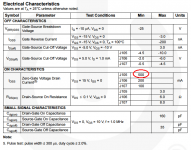
For small JFETs we can simply estimate Idss, input capacitance and Vgs(off).
Idss and Vgs(off) provides transconductance estimating while Ciss and transconductance are unable to be faked together.
For power devices can be used other method - loading test. Common fakes using small and cheap crystal inside huge TO-247/264 case. That crystals can't dissipate much heat, so just load it with rated power on a good heatsink and thermalgrease, wait some time and you're in.
There are one additional and useful tool - cheap transistor tester like this:
https://www.ebay.com/itm/142372146504
And one most actual question - originality of the FET.
For small JFETs we can simply estimate Idss, input capacitance and Vgs(off).
Idss and Vgs(off) provides transconductance estimating while Ciss and transconductance are unable to be faked together.
For power devices can be used other method - loading test. Common fakes using small and cheap crystal inside huge TO-247/264 case. That crystals can't dissipate much heat, so just load it with rated power on a good heatsink and thermalgrease, wait some time and you're in.
I measured a Fairchild J105 JFET (link to thread) using an oscilloscope and two $0.25 ICs on a solderless breadboard. Measured Idss was 1.10 amperes on this particular J105. I decided to use pulsed measurement techniques with low duty cycle (68 usec on, 330 msec off, 0.02% duty cycle) to avoid overheating.
_
_
Attachments
For the likes of J105, it is best to degenerate them before measurement.
You can either add a source resistor, or even a Zener Diode to create negative Vgs.
Alternatively, leave the gate open and use a current source (e.g. 10mA) at the drain.
And use the DMM to measure Vgs at that bias.
(Useful when used as cascode for other JFETs.)
Patrick
You can either add a source resistor, or even a Zener Diode to create negative Vgs.
Alternatively, leave the gate open and use a current source (e.g. 10mA) at the drain.
And use the DMM to measure Vgs at that bias.
(Useful when used as cascode for other JFETs.)
Patrick
Best is to measure Vgs and gm at the intended operating current. Diff amps and cascodes usually operate at waaaay less current than Idss. Source followers usually operate at or around Idss.
I myself am investigating the recommendation in AOE_3ed p.517, which suggests trying out the Fairchild J107 (IdssMin = 100mA) because of its surprisingly low noise. I'm measuring them (and extracting SPICE models) at the intended operating current, NOT at Idss. Even with relatively high velocity air blowing across the DUT, my parameter measurements @ 8mA DC drift up and down. So I'm working on low duty cycle pulse measurements + high velocity, constant temperature air.
BTW it's tough to measure gds (= dIds/dVds) with just a DMM. Peak Atlas Pro here we come!
It seems that Crss is also possible.
Current involved are ~ 1nA.
So the gate voltage needs a very high Zin buffer, such as LT1169.
And the input capacitance of the latter needs calibrating and subtracting from the final results.
Seems that one can really do a lot with a DMM, a sound card, and a LT1169 buffer.
Patrick
.
Current involved are ~ 1nA.
So the gate voltage needs a very high Zin buffer, such as LT1169.
And the input capacitance of the latter needs calibrating and subtracting from the final results.
Seems that one can really do a lot with a DMM, a sound card, and a LT1169 buffer.
Patrick
.
Attachments
The voltage reference V2 can of course be a resistor plus a Zener or a voltage reference, etc.
You can skip all these if you are not bothered with exactly 100% constant Vds between different FETs.
The Vds error involved would be small (< 0.5V), and will not affect matching between FETs.
While in the J111, the -Vgs is large enough for a CRD to work, this is not the case for the K170.
A 2SK170BL with 8mA Idss will have a mere -0.25Vgs at 1mA.
It is not so easy to find a 1mA CCS that will work with that little headroom.
So the tail of the CRD has to be at say 9~12V below Vg.
One can do it like the simplified schematics attached here.
Vdg is kept constant at 12V, and Vds will varies within a few tenths depending on Idss.
I guess you have a simpler solution to share ?
Patrick
.
Attachments
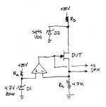
Opamp + NFB ensure that the source voltage equals the zener voltage of diode D1. Then the current IDS equals Vzener/Rs. I've set that to 1 mA but of course a TL431+trimpot instead of D1 would permit adjustment. A rotary switch to swap in different values of Rs would be nice too.
The source voltage is VzenerD1 and the drain voltage is VzenerD2 so VDS is just the difference between the two; choose D2 to get the VDS you want. Or make D2 a TL431+trimpot and now you can adjust VDS smoothly and continuously.
One power supply, a single opamp (RRIO not required), and two zener diodes. Small and simple. I'd recommend choosing the OP-07 due to its extremely low cost and good input offset voltage specs.
I'm not too fond of current regulating diodes, they seem too scarce, too costly, and their tolerances are looser than I prefer.
_
Attachments
Last edited:
Opamp controlled current source. Good solution.
May I suggest a protection diode from opamp out to DUT S, just in case D is not properly connected during DUT swap?
And maybe a 1k gate stopper after the anode.
CRDs are not expensive in Asia.
Of course you can always make one from a 2SK209 with a source resistor to trim current.
Would not take 100V though, as a E102 would.
Patrick
- Status
- This old topic is closed. If you want to reopen this topic, contact a moderator using the "Report Post" button.
- Home
- Amplifiers
- Pass Labs
- FET Measurements with Just A DMM