2200pF is ver high value.
any of these will do
https://www.mouser.in/c/passive-com...citors-mlcc-leaded|~Lead Spacing&sort=pricing
any of these will do
https://www.mouser.in/c/passive-com...citors-mlcc-leaded|~Lead Spacing&sort=pricing
Hi Prashant. Did the drill file get changed or corrupted? I have some boards now and notice the outer holes for the fast on tabs are smaller than they should be? Also noticed Harry's boards are the same. I can drill them out and I guess the solder and tab leg will do the job of the thru hole plating so not really an issue. Just wondered what happened! Thanks for the layout though and the kind sharing of the gerbers.
Hello,
the outer holes look smaller than center hole of tabs because they take up faston tab pins. whereas the center hole is meant to take up direct wire of 2.1 or 2.5 mm wire dire directly.
https://www.digikey.in/en/products/...-5E9U6SKUnBgYRcz2mu0PjlSBgQViGrBoCihwQAvD_BwE
the outer holes look smaller than center hole of tabs because they take up faston tab pins. whereas the center hole is meant to take up direct wire of 2.1 or 2.5 mm wire dire directly.
https://www.digikey.in/en/products/...-5E9U6SKUnBgYRcz2mu0PjlSBgQViGrBoCihwQAvD_BwE
outer ones are 1.6mm dia, easily take up fastons...
center hole is 2.54mm... enough for 13 gauge wire
center hole is 2.54mm... enough for 13 gauge wire
Hello,
some pix from my Prasi F5 with same Toshiba´s as in my M2OPS (Toshiba 2SK3497/2SJ618)..for comparison; 23,5V rails= Iq=1.35A
and some FFT measurements (LAB supply; Rigol DHO 1204--32averages)
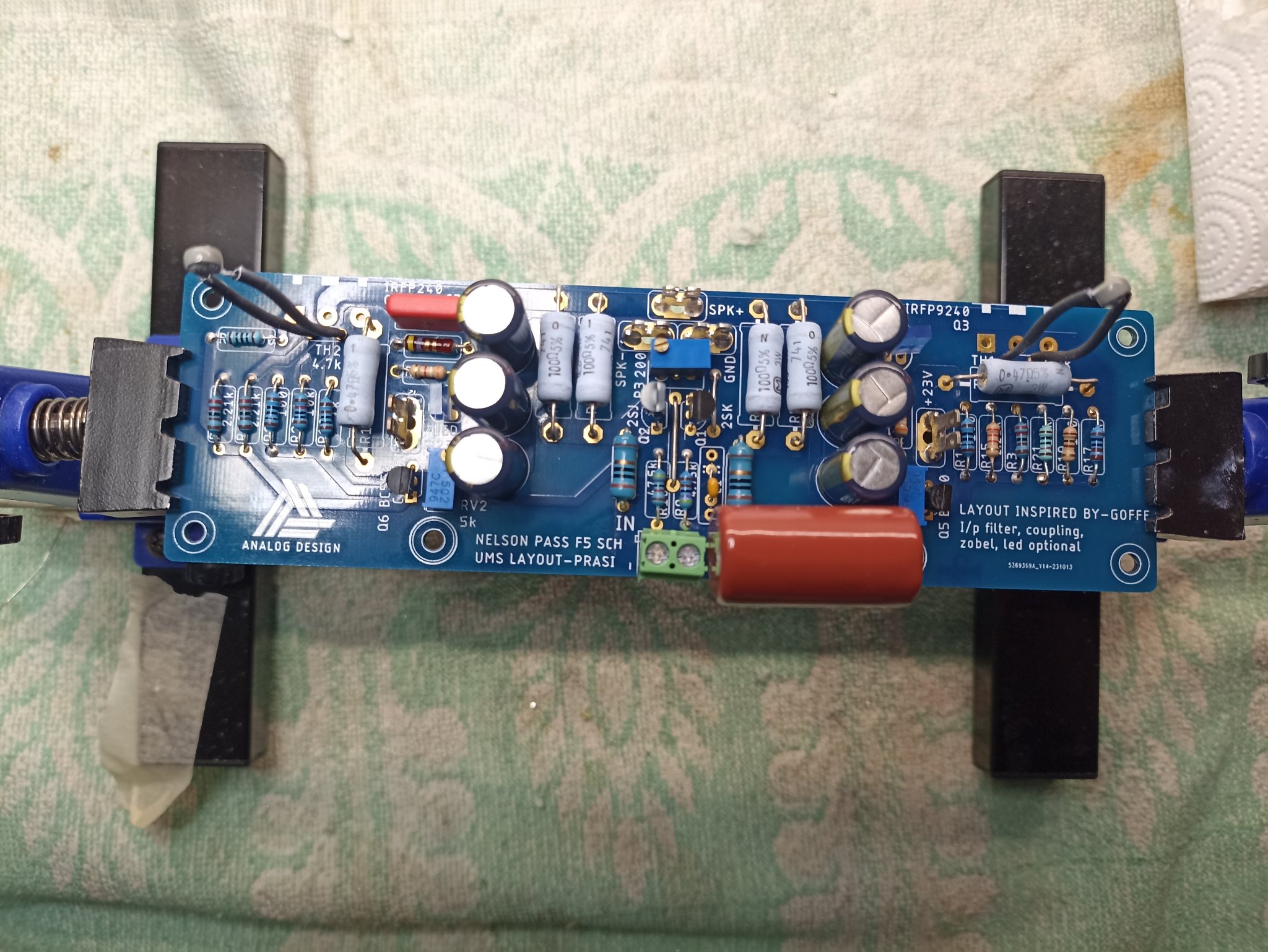

some pix from my Prasi F5 with same Toshiba´s as in my M2OPS (Toshiba 2SK3497/2SJ618)..for comparison; 23,5V rails= Iq=1.35A
and some FFT measurements (LAB supply; Rigol DHO 1204--32averages)
Attachments
-
 IMG_20240718_201516.jpg462.9 KB · Views: 523
 -
 FFT_R_8R_24W.png63.8 KB · Views: 89
 -
 FFT_R_8R_15W.png64 KB · Views: 80
 -
 FFT_R_8R_8W.png63.3 KB · Views: 74
 -
 FFT_R_8R_4W.png63.8 KB · Views: 88
 -
 FFT_R_8R_1W.png63.7 KB · Views: 93
 -
 FFT_R_4R_40W.png62.5 KB · Views: 92
 -
 FFT_R_4R_28W.png63.6 KB · Views: 73
 -
 FFT_R_4R_1W.png64.2 KB · Views: 75
 -
 FFT_R_4R_2W.png61.9 KB · Views: 77
 -
 FFT_R_4R_7W.png63.6 KB · Views: 68
 -
 FFT_R_4R_16W.png63.4 KB · Views: 77


1. I dont have an audio precision
2. NelsonPass measured with how many averages?
3. my SG is not so good but have no better things here...
Check with my Rigol DG1022, and not serviced Philips PM5105LF and Philips PM5106LF, tried 32avg and 512 avg.....
No wonder that EUVL built his own one 😉


2. NelsonPass measured with how many averages?
3. my SG is not so good but have no better things here...
Check with my Rigol DG1022, and not serviced Philips PM5105LF and Philips PM5106LF, tried 32avg and 512 avg.....
No wonder that EUVL built his own one 😉
Did you FFT the 1kHz signal only? You need to know the amount of distortion the oscilloscope displays with the test signal only.
An USB sound card and computer with software such as Room Equalization Wizard (REW) does a much better job at FFTs than lower consumer grade oscilloscopes.
https://www.diyaudio.com/community/threads/how-to-distortion-measurements-with-rew.338511/
An USB sound card and computer with software such as Room Equalization Wizard (REW) does a much better job at FFTs than lower consumer grade oscilloscopes.
https://www.diyaudio.com/community/threads/how-to-distortion-measurements-with-rew.338511/
Last edited:
A scope with a vertical resolution of 12 bit will have a hard time measuring under -20log(2^12 - 1) = -72.25 dB😉
@Ben Mah , yes I measurent direct from Sg........I it sad that my low consumer oscilloscope (€2200,-) can do special audio jobs....
I´m primarily interested in spectrum of H0 and H2,H3,H4,H5....i dont know if an error of 0,025% (-72dB) is so important and cant make the math how it has influence on the measurements.......
It sounds very good compared to M2OPS, different and bass is more rolling......, not so good contours of artists and depth....IMO
I do not understand what you mean by this.yes I measurent direct from Sg......
However, as I asked twice now, did you measure the signal direct from the signal generator, without the amplifier amplifying the signal?
In addition to oscilloscopes not being the best for FFTs, some signal generators have higher distortion than the amplifiers being measured.
So the distortion and noise in the measurement system need to be established first in order for the amplifier measurements to be meaningful.
Ok, so your amplifier measurements include the high distortion and higher modes of the signal generator.
As I mentioned previously a USB sound card and software such as REW can do a much better job of measuring amplifier distortion compared to a oscilloscope, and much less costly too.
As I mentioned previously a USB sound card and software such as REW can do a much better job of measuring amplifier distortion compared to a oscilloscope, and much less costly too.
- Home
- Amplifiers
- Pass Labs
- F5 layout