Because you would suddenly have a 3-cu.ft. amp that weighs 150 lbs. Most of these amps are large 'cause of heat sinks but that would be a litlte much..
Actually the larger the coil, the lower the low frequency rolloff, so you would ideally want a very large value, but there are limits of practicality to think about.
large coil also helps for PS filtering in the same way it extends low freq response..
Actually the larger the coil, the lower the low frequency rolloff, so you would ideally want a very large value, but there are limits of practicality to think about.
large coil also helps for PS filtering in the same way it extends low freq response..
hacknet said:sorry for the silly question but would having too much inductance have ill effects on the amp?
how does one come to the figure of 50mH?
I used about 1 Henry, as I wanted some bottom end. 50 mH
is only going to give you about 6 ohms worth of reactance
at 20 Hz. If you're operating above 100 Hz, it probably
would be perfectly adequate.
After quite a search, i found the thread i told about in an earlier post.
http://www.diyaudio.com/forums/showthread.php?s=&threadid=24737&perpage=15&highlight=&pagenumber=8
Magura")
http://www.diyaudio.com/forums/showthread.php?s=&threadid=24737&perpage=15&highlight=&pagenumber=8
Magura
Speakers with very low Qts are quite efficent and frequently vented.
Think classic Altec, JBL.
Venting these drivers to 30hz~40hz causes a peak in the impedance in the 60hz~70hz region.
It may be needed to add a 30 ohm resistor in parallel with the speaker for best operation.
Play it by ear.
Note:
This helps PP tube amps with small iron too.
Think classic Altec, JBL.
Venting these drivers to 30hz~40hz causes a peak in the impedance in the 60hz~70hz region.
It may be needed to add a 30 ohm resistor in parallel with the speaker for best operation.
Play it by ear.
Note:
This helps PP tube amps with small iron too.

Re: Is this a stupid question?
If you're going to increase the complexity, the next step up would
likely be an Aleph current source, which tracks against current,
essentially "ghosting" the load. That system would run at twice
the voltage and 1/2 the current, giving roughly the same efficiency
as a coil.
Stocker said:Instead of a 150lb. amplifier with multi-henry chokes-
-could a gyrator be used instead?
circuit complexity goes up but that has to be weighed ( ! ) against the cost and mass of all that copper.
If you're going to increase the complexity, the next step up would
likely be an Aleph current source, which tracks against current,
essentially "ghosting" the load. That system would run at twice
the voltage and 1/2 the current, giving roughly the same efficiency
as a coil.
i did look at the aleph current sources. it looks very much like those on the zen v2. is this correct?
if it is, i`m actually running into a problem. i don`t have enough heatsinking and enough budget to get another pair to do the job....
i did a rough calculation and found my zen lite`s mosfets to be dissipating roughly 25w since the source voltage is 12v and the current drawn is 2.1 ampere. the heatsinks get very hot. too hot to touch. i don`t know if these are because of the bulbs dissipating 240w in that small area or is it because of the fets.
my heatsinks are 9'' by 5" by 1.5" fins. can anyone help me determine if my heatsinks are big enough for a current souce?
i am using a 50v trans at the moment i have another 24v 12ampere trans waiting to be used. could the calculations be done for a 35v supply? thankyou for the help!
need some answers
Hi!
I try to ask one more time: would the attached circuit work as it is?
-and if : would a 2X16V -400VA transformer enough for two channel?
-what is the max voltage for this amp?
-what typ of the zener?
-is it possible to use IRFP240 instead of the BUZ900 without any change?
-needn't I adjust somhow the circuit? There isn't any trimmer..
Thanks!
Attachments
It *should* work as it is, but I think the power supply has to be regulated to avoid drifting bias.
16VAC gives ~22,5VDC after rectification (minus diode losses), which is a bit low if you´re going to regulate it.
I guess the circuit will work just as fine at slightly lower rail voltage, though.
I´d use a 12V zener.
IRFP240 should work fine AFAIK.
I´d replace that 4k resistor with a 4,7k trimmer in series with a 2,2k resistor.
You´re welcome.
I´ve spent a lot of time philosofing about similar circuits, and what did I come up with?
Getting high input impedance, low output impedance, stable bias,
low parts count and so on at the same time is not easy. Maybe not even possible.
Sacrifices has to be made somewhere, and it´s up to each designer to decide what to sacrifice.
The major drawback (according to me) in this schematic is the low input impedance. It cannot be "fed" from a CDP though a passive attuenator.
I´ve chosen another path towards nirvana, which is choke loaded Mosfet followers.
A 30 W balanced version is soon to be ready and I´m making plans for a bigger project in the future.
Not quite as elegant but way easier to mess around with.
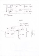
Old thread, but I had to give choke load a shot
Look at drawing.
Bias is about 1,4A and stable.
Sounds nice, but I do only use it from 600Hz and up on JBL horns.
Tried it on some small bookshelf speakers.
It played bass fine on the small speakers, but with the small 28mH chokes thinking it won't play lower than 45Hz or so...?
Also have som low frequency hum, but no problem on the horns.
Gain is also a bit low.
On the positive side it does not dissipate so much heat
Any tweaks to make it better is welcome!
Attachments
- Status
- This old topic is closed. If you want to reopen this topic, contact a moderator using the "Report Post" button.
- Home
- Amplifiers
- Pass Labs
- Choke Loaded Zen