Oh, and that's DEF i SIT.")
Perfect description for the state of my finances when you this available for sale.
.....
REVERSE THE POLARITY!!!!
that's easy
Attachments

REVERSE THE POLARITY!!!!
That's one small step for mankind, one giant leap for me [emoji3]
Perhaps you are referring to this?
Input transformer voltage gain?
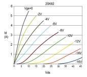
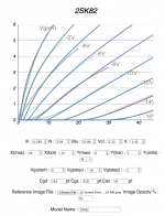
I have been using this Spice model made with Michael's nice SIT modeler. I don't know if if this one is better than the other, so please try this and let me know.
*--------------------------------------------------
.SUBCKT 2SK82 D G S ; Drain Gate Source
+ PARAMS: MU=10.86 X=1.42 K=0.198 N=3.09 VCT=2.32 RG=2MEG
*--------------------------------------------------
B1 D S I=K*PWR(URAMP((V(G,S)+VCT)+(N*LN(V(D,S))+(V(D,S)/MU))),X)
*FOR MULTISIM COMMENT OUT ABOVE LINE (*) AND UNCOMMENT NEXT LINE
*B1 D S I=K*PWR(MAX((V(G,S)+VCT)+(N*LN(V(D,S))+(V(D,S)/MU)),0),X)
R1 G S {RG}
CGS G S 319P
CGD G D 142P
CDS G S 42P
.ENDS 2SK82
*--------------------------------------------------
*--------------------------------------------------
.SUBCKT 2SJ28 D G S ; Drain Gate Source
+ PARAMS: MU=10.86 X=1.42 K=0.198 N=3.09 VCT=2.32 RG=2MEG
*--------------------------------------------------
B1 S D I=K*PWR(URAMP((V(S,G)+VCT)+(N*LN(V(S,D))+(V(S,D)/MU))),X)
*FOR MULTISIM COMMENT OUT ABOVE LINE (*) AND UNCOMMENT NEXT LINE
*B1 S D I=K*PWR(MAX((V(S,G)+VCT)+(N*LN(V(S,D))+(V(S,D)/MU)),0),X)
R1 G S {RG}
CGS G S 319P
CGD G D 142P
CDS G S 42P
.ENDS 2SK82
*--------------------------------------------------
*--------------------------------------------------
.SUBCKT 2SK82 D G S ; Drain Gate Source
+ PARAMS: MU=10.86 X=1.42 K=0.198 N=3.09 VCT=2.32 RG=2MEG
*--------------------------------------------------
B1 D S I=K*PWR(URAMP((V(G,S)+VCT)+(N*LN(V(D,S))+(V(D,S)/MU))),X)
*FOR MULTISIM COMMENT OUT ABOVE LINE (*) AND UNCOMMENT NEXT LINE
*B1 D S I=K*PWR(MAX((V(G,S)+VCT)+(N*LN(V(D,S))+(V(D,S)/MU)),0),X)
R1 G S {RG}
CGS G S 319P
CGD G D 142P
CDS G S 42P
.ENDS 2SK82
*--------------------------------------------------
*--------------------------------------------------
.SUBCKT 2SJ28 D G S ; Drain Gate Source
+ PARAMS: MU=10.86 X=1.42 K=0.198 N=3.09 VCT=2.32 RG=2MEG
*--------------------------------------------------
B1 S D I=K*PWR(URAMP((V(S,G)+VCT)+(N*LN(V(S,D))+(V(S,D)/MU))),X)
*FOR MULTISIM COMMENT OUT ABOVE LINE (*) AND UNCOMMENT NEXT LINE
*B1 S D I=K*PWR(MAX((V(S,G)+VCT)+(N*LN(V(S,D))+(V(S,D)/MU)),0),X)
R1 G S {RG}
CGS G S 319P
CGD G D 142P
CDS G S 42P
.ENDS 2SK82
*--------------------------------------------------
Attachments
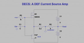
Nelson Pass hints at "reversing the polarity" and the name DEF -i-SIT with an "i". The "i" could mean "inverted"?
Jfets can work with inverted voltages...

I believe - reverse the polarity - was hint for some previously posted schematic
The earlier schematic by gior showed its 2SJ28 with a reversed polarity VdsI believe - reverse the polarity - was hint for some previously posted schematic
My apology gior as I am mistaken in my above post. The Vds polarity for 2SJ28 as shown in your schematic is correct. The grounded source of 2SJ28 is positive relative to its drain. The polarity of V [colector-emitter] for PNP is also correct. The Vds for P-Mosfets is also proper. The top right part of the amp schematic shows a negative power rail relative to ground.The earlier schematic by gior showed its 2SJ28 with a reversed polarity Vds
Six Easy (P)ieces
Here are a few of my thoughts. In keeping to the "simple" criteria, I have traded some things like gain or voltage swing for fewer power supplies and so forth. This is my homage to Nelson Pass's homage to Richard Feynman
Here's the link:
Six Easy (P)ieces
#1,#2 The usual suspects in antimatter form
#3 A follower for light bulb lovers
#4 A little two-stager
#5 A potentially fun little circuit, SE/PP selectable
#6 An even simpler circlotron, for those who weren't crazy about all the supplies in the V-FETRON.
If one of these bubbles to the top, let me know and we'll flesh it out further.
Tks Mr. MR!Here are a few of my thoughts. In keeping to the "simple" criteria, I have traded some things like gain or voltage swing for fewer power supplies and so forth. This is my homage to Nelson Pass's homage to Richard Feynman
Here's the link:
Six Easy (P)ieces
#1,#2 The usual suspects in antimatter form
#3 A follower for light bulb lovers
#4 A little two-stager
#5 A potentially fun little circuit, SE/PP selectable
#6 An even simpler circlotron, for those who weren't crazy about all the supplies in the V-FETRON.
If one of these bubbles to the top, let me know and we'll flesh it out further.
Could you help me the value of that resistors, trims and bias in schm (6)!
Best Regards
Jamahamvui.
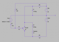
2SJ28 SE with a common +-24V supply.
I drew this a while ago but I don't know if this works well in real world. On Spice, Bias is 19.3V and 2A and THD figure is OK. Bias can be adjustable like Mike does on #3 above.
PS: I guess this one requires a very quiet CLC type supply, and/or it can be used as a tweeter amp cutting the low frequency decreasing the value of C5. I'll try this soon and will report.
Attachments
Last edited:
Let's talk seriously about potential 2SJ28 amp structure choices: front-end with output stage.
DEF with vfet is ready made by Mr.NP and sound fantastic !
Could we design different amplifier with touch of new "innovate" elements ?
Sony's 28 is only two pcs, not matched in lucky Diyer's drawers i guess...
My proposition:
Front-end | muscle 2SK79 with autoformer striped Edcor gain stage.
+ use of available small signal Sony's so we get new amplifier with two different triode semi's.
Output stage | Single-ended with CCS
+ low distortion , THD with frequency response are relatively flat, efficiency.
Bear with me ~ thoughts ?
Guys please any answer
Attachments
Here are a few of my thoughts. In keeping to the "simple" criteria, I have traded some things like gain or voltage swing for fewer power supplies and so forth. This is my homage to Nelson Pass's homage to Richard Feynman
Here's the link:
Six Easy (P)ieces
#1,#2 The usual suspects in antimatter form
#3 A follower for light bulb lovers
#4 A little two-stager
#5 A potentially fun little circuit, SE/PP selectable
#6 An even simpler circlotron, for those who weren't crazy about all the supplies in the V-FETRON.
If one of these bubbles to the top, let me know and we'll flesh it out further.
Excellent work Sir Rothacher that interesting topology schematics.
Well good reason for more thinking, reflections.Write my response tomorrow.
Greetings


A simple test with a battery biased SRPP dynamic current source and a 2SJ28 as a source-follower.
10+10 volt P-P input gives 7+7 volt P-P output. The 2SJ28 does not have a lot of transconductance. I am used to the IRFP7430 and IXTH140P05T so the 2SJ28 seems very weak and "soft".
#1,#2 The usual suspects in antimatter form
#3 A follower for light bulb lovers
#4 A little two-stager
#5 A potentially fun little circuit, SE/PP selectable
#6 An even simpler circlotron, for those who weren't crazy about all the supplies in the V-FETRON.
If one of these bubbles to the top, let me know and we'll flesh it out further.
They all bubble to the top. I think #5 is particularly cute.


The same setup but with a 10 ohm resistor as a couple of lightbulbs.
10 + 10 volt input gives 5.8 + 5.8 volt output.
It has 0.58 X voltage-gain. This is something to consider when designing the first gain-stage. I would prefer an autoformer as a voltage gain stage.
Cheers,
Johannes


An IRFP7430 in the same kind of source-follower and the same 10 ohm power-resistor as light-bulb source-load. The distortion drops by a factor of 10. The output-voltage is virtually the same as the input-voltage.
The irfp7430 is my all time favorite mosfet for source-follower duty.
I don´t mean to bash the 2SJ28, but I don´t understand why one would like to use one to drive loudspeakers. The 2SJ28 lacks transconductance, which can be seen in the large loss of voltage-swing.
The IRFP7430 has the same kind of transfer curves but is a modern device with lots of power.
- Status
- This old topic is closed. If you want to reopen this topic, contact a moderator using the "Report Post" button.
- Home
- Amplifiers
- Pass Labs
- What To Do With Those 2SJ28's