Just finishing up some woodwork today.Poly coat tonight.
The big ones are "L'Amp Revisited".
" L'Amp Revisited " that very interesting news
Test fitting some stuff.
Superb mono block's
wood work looks perfect
Bravo
I am currently listening to this:
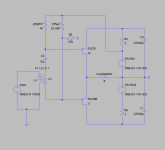
I've spent some time simulating this one with 2sj28 in spice and it looks interesting. I thought I may try it with parts I have around. The transformers I have however are the F6 ones and their data-sheet says no DC at the primaries so not the best choice I guess. Anybody can confirm this? Thanks
I've spent some time simulating this one with 2sj28 in spice and it looks interesting. I thought I may try it with parts I have around. The transformers I have however are the F6 ones and their data-sheet says no DC at the primaries so not the best choice I guess. Anybody can confirm this? Thanks
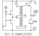
...That was the circuit in post 96

For what it's worth,
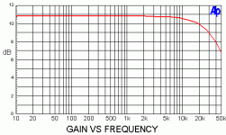
The simplified schematic of post #96 is now the SIT-3, and I have the pilot
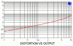
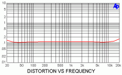
production run near completion. Below is that image and also three
graphics of measurements on it.
Nice thing about this particular circuit is that accommodates all the remaining
SIT devices including the Sony parts, and you just reverse the polarities for
P vs N channel SITs.
The second piece of news is that the Sony VFET project has turned out
sufficiently reliable that I can release some of the VFETs that were being held
against repair needs, so I think we will be making arrangements shortly for
a small offering. Looks like one more chance to get in on the VFET action
for those who missed the three previous releases.
And if you miss this one, the circuit works fine with a regular Fet as well.
The simplified schematic of post #96 is now the SIT-3, and I have the pilot
production run near completion. Below is that image and also three
graphics of measurements on it.
Nice thing about this particular circuit is that accommodates all the remaining
SIT devices including the Sony parts, and you just reverse the polarities for
P vs N channel SITs.
The second piece of news is that the Sony VFET project has turned out
sufficiently reliable that I can release some of the VFETs that were being held
against repair needs, so I think we will be making arrangements shortly for
a small offering. Looks like one more chance to get in on the VFET action
for those who missed the three previous releases.
And if you miss this one, the circuit works fine with a regular Fet as well.
Attachments
Great News!
Can you give guidance on the following?
On circuits comparing single and paralleled devices there seems a big improvement in noise -is this just a general rule of thumb or can one predict this (and if so how?)?
If you wanted a balanced input would it make more sense to build four SE amps and bridge them or build a preamp to accept balanced input and then parallel output devices?
If one uses 2SK180 devices what kind of output figures would you expect to see?
Cheers
PS where do we sign up - I joined the forums to recently and missed the earlier opportunities....
PPS. THANKS!
On circuits comparing single and paralleled devices there seems a big improvement in noise -is this just a general rule of thumb or can one predict this (and if so how?)?
If you wanted a balanced input would it make more sense to build four SE amps and bridge them or build a preamp to accept balanced input and then parallel output devices?
If one uses 2SK180 devices what kind of output figures would you expect to see?
We have to decide whether we are talking about the internal noise of
devices or the noise they fail to reject.
Generally paralleling devices for lower internal noise is for low level circuits
like phono inputs, where, for example, the input noise is improved by 3 dB
for two devices instead of one.
If we are talking about output stages, we are not looking for internal noise
improvements, rather higher transconductance and dissipation capacity
as the benefits.
With SITs, it's more complicated yet, as parallel devices reduce the
power supply rejection due to the low Drain impedance. SITs do not
reject supply noise well, and balanced operation here can be helpful.
Given all the variables, though, there is no blanket solution.
...
With SITs, it's more complicated yet, as parallel devices reduce the
power supply rejection due to the low Drain impedance. SITs do not
reject supply noise well, and balanced operation here can be helpful...
If 2 K180s are indeed paralleled in the upcoming circuit for increased output, would driving rail voltage with a low-noise (<1mV ripple), linear bench supply be workable and advisable?
The lower the supply noise, the better. Switching bench supplies are
sometimes problematic because it's not simple ripple - there's lot of
higher frequency components, so I end up filtering it passively.
That said, the SIT does not have to reject ripple in the circuit above -
the Drain is attached to ground. It is the constant current source that
is responsible for the power supply noise rejection.
That's what is clever about that circuit.
as I said numerous times (though , certainly not responsible for inventing it ) - Ground is just state of mind
( so , when constructor is clever enough , he can deliberately ground positive end of PSU)

everything is easier post hoc
(hey , did I invent that , right now ? )
( so , when constructor is clever enough , he can deliberately ground positive end of PSU)
everything is easier post hoc
(hey , did I invent that , right now ? )
Attachments
Looking at the SIT-3...
If one wanted a balanced input, would connecting the two outputs of the BBA-3 balanced preamp to
i) the junction of the capacitor/transformer and
ii) the junction of the outputs of the input pair and the transformer?
Is this a reasonable solution?
thanks
If one wanted a balanced input, would connecting the two outputs of the BBA-3 balanced preamp to
i) the junction of the capacitor/transformer and
ii) the junction of the outputs of the input pair and the transformer?
Is this a reasonable solution?
thanks
One would drive one of the coils isolated, leaving the others in series to
give slightly less than 10 dB gain.
The input coil can be driven single-ended or balanced.
Keep in mind that you want the source impedance low or you will see
more distortion. This one has about 20 ohms source impedance.
give slightly less than 10 dB gain.
The input coil can be driven single-ended or balanced.
Keep in mind that you want the source impedance low or you will see
more distortion. This one has about 20 ohms source impedance.
I am currently listening to this:
Hello Mr.Pass. A stereo diySIT-3 maybe:
1. Both channels using identical 2SJ28s.
2. Both channels using identical 2SK82s.
3. One channel using 2SJ28, and the other channel using its complementary 2SK82
The resultant 6 channels are expected to have a similar objective high performance. My hypothesis is that stereo #3 is expected to have a sound which is subjectively different; better or worse than either #1 or #2.
Most probably you've already listened to all 3 SIT-3 stereos and have the winner.
- Status
- This old topic is closed. If you want to reopen this topic, contact a moderator using the "Report Post" button.
- Home
- Amplifiers
- Pass Labs
- What To Do With Those 2SJ28's