Digikey also have kapton insulators,
http://www.wakefield.com/pdf/Accessories.pdf
(5th page...175-6 series is available)
However, as AudioFreak mentioned, maybe pressure could be a problem. They recommend a pressure of 350-550 lb/in². How much is that...I have absolutely no idea. They give a formula to compute the torque required, but it doesn't help me much.
Edwin, the thermal resistance from fischer is stated in K/W... I'm sure this is not Kelvin/Watt... is K mean Celsius in Danemark? Talking about Danemark, I realize that I won't be able to order from them. I'll seek for the same product from another distributor.
regards,
Gabriel
Gabster,
Your sim is unfortunately way way off. Have a look at the one I did on the passdiy site in my article. You can see that the transistors have a large effect on each other. That is, six sinks with six transistors will sim very differently than one sink with six transistors. I urge you to experiment to get a feel for what will happen to the temps. Take a large sink and run sims with different numbers of devices, different powers, and use the correct size for the devices too or also vary this to see what happens. I guarantee you are in for an education on thermal circuits") . After 5 or 6 sims with varying parameters you begin to get a "feel" for what happens.
. After 5 or 6 sims with varying parameters you begin to get a "feel" for what happens.
If you're getting junction temps any lower than 95C you're almost certainly doing something wrong unless you have a X-1000 sized case.
While you're at it, if it's not too much trouble for you, why don't you post your experiments - there are many around these forums who don't understand thermal rejection, and it is really at the heart of a Class A amp..... just an idea.
Don't forget to add 0.8 C per watt for the die-to-case thermal delta, and maybe 0.5 C to 1.5 C per Watt for your insulator - i think you already know you have to take this into acount. The pads I used were only 0.5C/W and this is about as good as it gets.
On the plus side, the sim doesn't take into account the heat that the top, front, and rear of the chassis will be sucking off the edges of the sinks, this will give you back maybe 2 or 3C I'd wager, though I can't prove it.
Also on the negative side, the sim assumes a 75C rise over ambient which you won't have (you'll be in real trouble of you do.....it'd mean a sink with a temp around boiling point of water and huge junction temps), there are resources on the site that tell you how to derate for this factor.
Good luck Gabster, I hope I'm not coming across as too harsh or negative here but you're heading for a problem I think given your sim.
Your sim is unfortunately way way off. Have a look at the one I did on the passdiy site in my article. You can see that the transistors have a large effect on each other. That is, six sinks with six transistors will sim very differently than one sink with six transistors. I urge you to experiment to get a feel for what will happen to the temps. Take a large sink and run sims with different numbers of devices, different powers, and use the correct size for the devices too or also vary this to see what happens. I guarantee you are in for an education on thermal circuits
. After 5 or 6 sims with varying parameters you begin to get a "feel" for what happens.If you're getting junction temps any lower than 95C you're almost certainly doing something wrong unless you have a X-1000 sized case.
While you're at it, if it's not too much trouble for you, why don't you post your experiments - there are many around these forums who don't understand thermal rejection, and it is really at the heart of a Class A amp..... just an idea.
Don't forget to add 0.8 C per watt for the die-to-case thermal delta, and maybe 0.5 C to 1.5 C per Watt for your insulator - i think you already know you have to take this into acount. The pads I used were only 0.5C/W and this is about as good as it gets.
On the plus side, the sim doesn't take into account the heat that the top, front, and rear of the chassis will be sucking off the edges of the sinks, this will give you back maybe 2 or 3C I'd wager, though I can't prove it.
Also on the negative side, the sim assumes a 75C rise over ambient which you won't have (you'll be in real trouble of you do.....it'd mean a sink with a temp around boiling point of water and huge junction temps), there are resources on the site that tell you how to derate for this factor.
Good luck Gabster, I hope I'm not coming across as too harsh or negative here but you're heading for a problem I think given your sim.
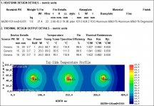
I've run another simulation using a very similar heatsink but 16.7" wide instead of 3x5".
Setup
Extrusion#: 66290
Source: 25W
Rcj: 0.83ºC/W
Rimp: 0.40ºCin²/W (digikey's kapton)
I guess that the casing/aluminum bars will counterbalance for the 1.7" missing on the 3x5" heatsinks.
How bad is this?
110ºC at junction...
64-65ºC at heatsink's outer edge...
regards,
Gabriel
Setup
Extrusion#: 66290
Source: 25W
Rcj: 0.83ºC/W
Rimp: 0.40ºCin²/W (digikey's kapton)
I guess that the casing/aluminum bars will counterbalance for the 1.7" missing on the 3x5" heatsinks.
How bad is this?
110ºC at junction...
64-65ºC at heatsink's outer edge...
regards,
Gabriel
Attachments
My opinion is that 110C is too high. You should shoot for 100 or less. Also, you want to try to get the highest exposed temp (the middle top of the baseplate) to be 50C or less.
Can you increase the height of the extrusion to, say 8 or 9" ??? This will give you a few more degrees, and then the entire side of the amp is heatsink, which is what you will find you need after all this (he said, knowingly...).
Can you increase the height of the extrusion to, say 8 or 9" ??? This will give you a few more degrees, and then the entire side of the amp is heatsink, which is what you will find you need after all this (he said, knowingly...).
Well, the time has come to take a decision. I will build the chassis with the actual considerations (junction at 110ºC). If it turns out that the junctions really run at that temperature (Wayne, you stated that the simulation results were hotter than the actual output), I will add an extra heatsink above FETs, between the two rows of heatsinks. This should do the trick.
110ºC is not critical and won't kill the FETs right away. It will be easier once everything is built to experiment and settle down on effective solutions.
ciao,
Gabriel
P.S.: One more thing, IF the results of that experiment are catastrophic, would it be possible to simple lower the bias current?
P.S.S.: (5 mins later) Well, maybe I'm to optimistic and this will be catastrophic. Maybe I should run a test before. As I already asked before, how could I run a test circuit to have an IRFP244 outputing 25W of heat (if possible, using a ±28Vdc PSU). This way I would be able to make all possible measurements without spending 100$'s right away.
Gabster said:Digikey also have kapton insulators,
http://www.wakefield.com/pdf/Accessories.pdf
(5th page...175-6 series is available)
However, as AudioFreak mentioned, maybe pressure could be a problem. They recommend a pressure of 350-550 lb/in². How much is that...I have absolutely no idea. They give a formula to compute the torque required, but it doesn't help me much.
Edwin, the thermal resistance from fischer is stated in K/W... I'm sure this is not Kelvin/Watt... is K mean Celsius in Danemark? Talking about Danemark, I realize that I won't be able to order from them. I'll seek for the same product from another distributor.
regards,
Gabriel
Kelvin is Absolute temperature where as, Celcius is referenced to the freezing point of water under 1 atmosphere of pressure... change in temp of 1º Kelvin = change in temp of 1º Celcius
Typical mounting pressure of mosfets is below 20lb/in². So in that situation you can totally forget the rated thermal resistance.... also, my comment above applies to these kapton insulators in that they have poor gap filling ability and under most circumstances will require grease.
Gabster,
At the end of the day, my Alephs are as hot as I'd want them. That means that your models should have as much ability to reject heat as mine overall, otherwise they'll be running hotter.
Don't forget here that high temps on the sinks heat up all the other components in the amp.... you've got all these parts inside a chassis whose sides are around 60C, so any part that does its own heating (like the toroid, the input current source and the differential pair) will have a 60C ambient and so run hotter than that. To help this I considered having slots or holes cut into the tops and bottoms to get some airflow thru the middle of the amp as well as the external surfaces.... you might want to do this from the get-go.
Later....
- Status
- This old topic is closed. If you want to reopen this topic, contact a moderator using the "Report Post" button.
- Home
- Amplifiers
- Pass Labs
- Real "cool" R-Theta heatsink simulation