Pass DIY Addict
Joined 2000
Paid Member
**** happens ;-)
today should be the happy day to get the first channel set up. but it wasn't exactly")
after the powering up my first channel (without vfets installed) i smiled happily seeing the LEDs going on and got mentally ready to check the voltages. however, my smile was rapidly gone as i saw smokes coming out from both side of the board
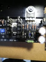
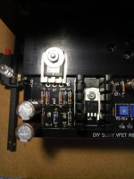
i quickly disconnected the mains and checked for the source of the smoke and saw that the R5, R6, R29 and R30 are smoked away! (please see the images)
inspection the board revealed that i had forgotten to solder the Q7 and Q8 after mounting them on the T-bracket :-(
my questions now please :
- could be this the reason for firing the resistors away?
- do you think any other components , especially the semiconductors could be damaged as well? (optically i can not see any other damaged/suspect components)
other point is that because of the 3P20 and 3N30 on board, i am using 1K for the P3 and P4 which i have found locally. this potentiometers have smaller housings (but the same power rating) than the 500 ohm ones delivered with the kit. as i measured them i found that they behave opposite to the other bigger 500 ohm. so before powering up the board i set the P3 and P4 fully clockwise and not counterclockwise!
- could this be also one reason why the R5 and R6 gone? shall i keep setting the P3 and P4 fully counterclockwise as instructed despite the opposite behaviour of the new potentiometers?
- any other suggestions what else might be responsible for destroying the resistors?
many thanks for your supports!
today should be the happy day to get the first channel set up. but it wasn't exactly
after the powering up my first channel (without vfets installed) i smiled happily seeing the LEDs going on and got mentally ready to check the voltages. however, my smile was rapidly gone as i saw smokes coming out from both side of the board
i quickly disconnected the mains and checked for the source of the smoke and saw that the R5, R6, R29 and R30 are smoked away! (please see the images)
inspection the board revealed that i had forgotten to solder the Q7 and Q8 after mounting them on the T-bracket :-(
my questions now please :
- could be this the reason for firing the resistors away?
- do you think any other components , especially the semiconductors could be damaged as well? (optically i can not see any other damaged/suspect components)
other point is that because of the 3P20 and 3N30 on board, i am using 1K for the P3 and P4 which i have found locally. this potentiometers have smaller housings (but the same power rating) than the 500 ohm ones delivered with the kit. as i measured them i found that they behave opposite to the other bigger 500 ohm. so before powering up the board i set the P3 and P4 fully clockwise and not counterclockwise!
- could this be also one reason why the R5 and R6 gone? shall i keep setting the P3 and P4 fully counterclockwise as instructed despite the opposite behaviour of the new potentiometers?
- any other suggestions what else might be responsible for destroying the resistors?
many thanks for your supports!
Attachments
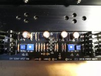
Okay, I didn't check every detail of your pics and post, but I believe your Q5 and Q6 are populated incorrectly.
Q5 (left position) is supposed to be P channel, so either 2SJ313 or FQP3P20. Q6 (right position) is supposed to be N channel, so either 2SK2013 or FQP3N30.
Not sure what your Q7 (IRFP240) and Q8 (IRFP9240) are populated with, but check them as well.
The TL431 get scared easily, plus they're cheap parts, so my advice is to replace them all as well.
...
Q5 (left position) is supposed to be P channel, so either 2SJ313 or FQP3P20. Q6 (right position) is supposed to be N channel, so either 2SK2013 or FQP3N30.
...
many thanks rodeodave, you are fully right i have the Q5 and Q6 switched :-(
do you think they are damaged now, shall i replaced them too?
nochmals vielen dank and best regards
If you look at the datasheet of the FQP, there is an intrinsic diode inside of the part. Applying reverse polarity will lead to conduction of current through this diode. This should in theory protect the FET, so I would think they had a pretty good chance of survival. Only testing will tell, either in circuit by verifying operation, or out of circuit.
Optimistically, only the parts which are involved with current through Q5 and Q6 may be damaged. That means that all the regs (TL431, IRF/IRFP) could still be fine. No guarantee though.
Optimistically, only the parts which are involved with current through Q5 and Q6 may be damaged. That means that all the regs (TL431, IRF/IRFP) could still be fine. No guarantee though.
many thanks, rodeodave,
i have plenty of TL431 around and the Q5 and Q6 are cheap parts as well , so i will probably replace them all to be on the safe side ;-) . even i can purchase ZTX450 (Q3) and ZTX550 (Q4) locally if it is necessary.
with the kit i received matched pair for the Q1 and Q2 (LSK170 and LSJ74) . do you know what is the difference of those one to the "normal" 2SK170-BL and 2SJ74-BL (or 2SJ74-GR)? is the "LS" the "low noise" version or the "2S" ?
just in case i need to replace them too, do they have to be matched or one can use unmatched pairs as well? ( i am not sure if the unmatched pair or Q1 and Q2 will lead to a significant non-linearity at the output with the thermal drift ? ) diyaudio-sore does not have currently any matched pair available.
best regards
The "2S" parts were made by Toshiba and were discontinued a number of
years ago. The "LS" parts are made by Linear Systems. They are meant to be
functionally equivalent replacement of the discontinued Toshiba parts.
many thanks, dennis. do the Q1 and Q2 have to be matched?
I would try to measure the Idss and match them; I wouldn't put in random parts.
ok, thanks a lot, dennis.
I'll suggest you head over to the article section on firstwatt.com and read all the VFET related articles, especially http://www.firstwatt.com/pdf/art_sony_vfet_pt2.pdf. It has the answers to all your previous questions.
I'll suggest you head over to the article section on firstwatt.com and read all the VFET related articles, especially http://www.firstwatt.com/pdf/art_sony_vfet_pt2.pdf. It has the answers to all your previous questions.
many thanks, rodeodave. i will surely do that.
best regards
just a short update regarding my progress . all spare parts received and replaced. i could manage to set the front-end. actually not so difficult but the offset is extremely sensitive regarding the position of the trimmers. one have the impression that the value changes with even looking at them ... the more interesting is that it seems to stay stable once it is set up .
currently following values i get:
R5 = 1502 mV
R6= 1496 mV
R31= 0 - 40mV
T16 and T17 are set according to the starting bias for the VFETs within 3 mv.
i am going to mount the VFETs this evening .
best regards
. all spare parts received and replaced. i could manage to set the front-end. actually not so difficult but the offset is extremely sensitive regarding the position of the trimmers. one have the impression that the value changes with even looking at them ... the more interesting is that it seems to stay stable once it is set up .currently following values i get:
R5 = 1502 mV
R6= 1496 mV
R31= 0 - 40mV
T16 and T17 are set according to the starting bias for the VFETs within 3 mv.
i am going to mount the VFETs this evening .
best regards
I'm just curious if anyone has compared this DIY amp to an Aleph J DIY? If so, what are the sonic differences? Is one clearly better than the other? I'm in the early stages of choosing which one I may end up building (if I can find stock for all the parts).
Thanks!
I have build Aleph J and Sony VFET - both great amps! I am single ended guy ;-) so I prefer Aleph J, but it is just my opinion...
I have build Aleph J and Sony VFET - both great amps! I am single ended guy ;-) so I prefer Aleph J, but it is just my opinion...
How would you describe the differences in sound between them? Which is more detailed, which has better bass control, which has a more 3D soundstage?
I have both, both are very nice and have that Pass family sound. But in my system I feel the VFET is a bit more dynamic/faster, seems to start and stop on a dime. I'm sure that any preferences would be system dependent. The VFET build is certainly more involved, but well worth it.
PJN
PJN
How would you describe the differences in sound between them? Which is more detailed, which has better bass control, which has a more 3D soundstage?
In my setup VFET is quicker, more dynamic, more 3D soundstage and I think it has better bass control as well. Aleph J just sounds really pleasant, especially in mid range, warmer, closer, great vocals, probably better tonal balance.
And another thing - Aleph J is quite easy to build and set up, Sony VFET I could never stop fiddling with pots...
Last edited:
- Home
- Amplifiers
- Pass Labs
- Sony vFET Illustrated build guide