Voltages on T6-T11 & T8-T13
Hi,
I have readings on T6-T11 & T8-T13 of 12 volts
This applies to both PCBs.
In "PART 2 - Applying power to the front end"
Initial voltages for these test points are specified
as ~5V.
Is this a concern?
VFets not mounted.
All the other test points are good. Altho I did
setup T6-T7 & T8-T13 to 1.2 volts with ~3.8mV on T18.
-ICHI
Last edited:
Are you using Fairchild mosfets and 1K pots for P3 and P4? If so, I think those
value are ok.
Cheers,
Dennis
I'm using 2sj313 & 2sk2013 Tosh, I believe, mosfets from NicMac and using 1k pots.
I think those values are ok for 1k pots.
Cheers,
Dennis
Thanks!
I just did a reading of T14 = 16v2 & T15 = 11v7 .
The revised schematic shows 13+-volts on the chart.
I guess the jfets are ok with that, I guess they're good
up to near 30volts.
hoopy frood noun. - an exceptionally cool and/or amazing ("hoopy") person who really has their act together ("frood").
Yes you are!
I bought mosfets from you ages ago (2008) for my first Pass amp, the F5.
Last edited:
Do I need to step down the voltages across R5/6? tia.
If the amp is fully warmed up (with lid on) then I wouldn't worry about it.
Maybe it's time for some listening in stereo.
Dennis
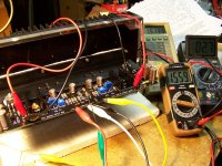
Powered up and setup the frontends of one then the second pcbs.
Got 1v5 on R5 & R6 with T18 sitting at 2.7mV.
Then setup T16 & T17 for the VFet bias.
(This was tweaked to these settings after a 2 hour warm up).
Tomorrow I will install the VFets and continue
with "PART 4 INSTALLING VFETS AND ADJUSTMENT"
-ICHI
Got 1v5 on R5 & R6 with T18 sitting at 2.7mV.
Then setup T16 & T17 for the VFet bias.
(This was tweaked to these settings after a 2 hour warm up).
Tomorrow I will install the VFets and continue
with "PART 4 INSTALLING VFETS AND ADJUSTMENT"
-ICHI
Attachments
Uh-Oh! Bad ju-ju!
-Not good.
Installed VFets.
First board biased up perfect.
Problem with second board.
Voltage across R32 will not go over 7mA.
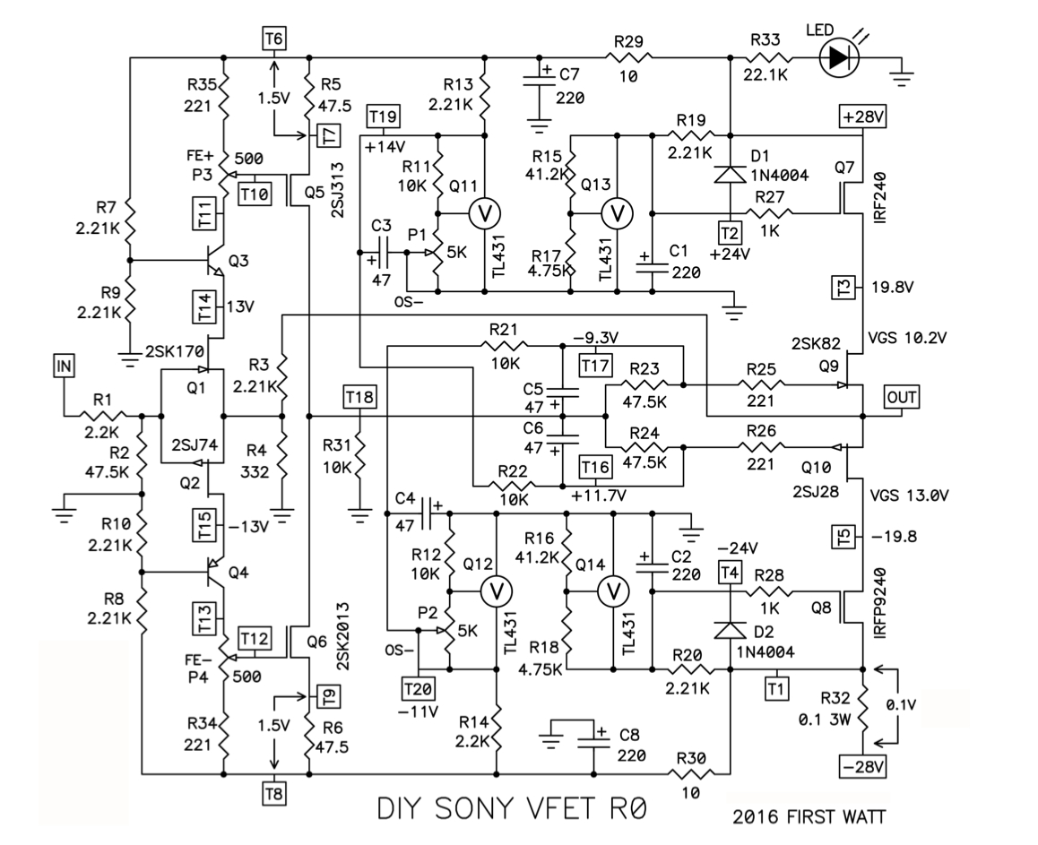
Here are voltages on all test points.
T1 -29v6
T2 +23v6
T3 +21v1
T4 -0v27
T5 +38mV
T6 +29v9
T7 +27v9
T6-T7 1v5
T8 -29v3
T9 -27v8
T8-T9 1v5
T10 +25v7
T11 +17v3
T12 -25v6
T13 -17v2
T14 -13v9
T15 -13v8
T16 +16v6
T17 -13v2
T18 +2v2
T19 +19v6
T20 -16v5
------------------------------------------- SOS
-Not good.
Installed VFets.
First board biased up perfect.
Problem with second board.
Voltage across R32 will not go over 7mA.
Here are voltages on all test points.
T1 -29v6
T2 +23v6
T3 +21v1
T4 -0v27
T5 +38mV
T6 +29v9
T7 +27v9
T6-T7 1v5
T8 -29v3
T9 -27v8
T8-T9 1v5
T10 +25v7
T11 +17v3
T12 -25v6
T13 -17v2
T14 -13v9
T15 -13v8
T16 +16v6
T17 -13v2
T18 +2v2
T19 +19v6
T20 -16v5
------------------------------------------- SOS


Why can I not leave well alone. My amp was working; playing music but it bugged me that one channel had higher offset readings both at the output and at g-T18. This morning I tried to reset things, the good? channel I was able to achieve even better readings getting -25mv at both. The other board readings are now all over the place with G-T19 close to 1 volt and output offset at 655mv. Would folk advise that I remove the Vfets and start again with setting the voltages? Please tell me I haven't fried the vfets
. My amp was working; playing music but it bugged me that one channel had higher offset readings both at the output and at g-T18. This morning I tried to reset things, the good? channel I was able to achieve even better readings getting -25mv at both. The other board readings are now all over the place with G-T19 close to 1 volt and output offset at 655mv. Would folk advise that I remove the Vfets and start again with setting the voltages? Please tell me I haven't fried the vfetsif it responds when you fiddle with trimpots , you didn't fried them
safest way is certainly to remove VFets and start setting of FE from scratch
I would do it with F1A25 in rails , without removing anything , but I'm lazy and stubborn and even can't remember when I started ruining electronic things ...... so better safe than sorry
safest way is certainly to remove VFets and start setting of FE from scratch
I would do it with F1A25 in rails , without removing anything , but I'm lazy and stubborn and even can't remember when I started ruining electronic things ...... so better safe than sorry
Hey Mighty ZenMod,
Should removing the vfets prove difficult, can one first increase the gate voltages
with P1 and P2 to turn off the vfets and then temporarily remove R3 to break
the feedback. After biasing up the front end, add back R3 and then bias
the vfets?
(Referring to schematics here:
https://www.diyaudio.com/archive/gallery/data/500/Vfet_Schematic.jpg )
Just thinking (out loud) to try biasing up the FE in isolation; not sure if this actually helps.
Thanks,
Dennis
Last edited:
- Home
- Amplifiers
- Pass Labs
- Sony vFET Illustrated build guide