I imagine this article is child's play for many of the DIY crowd, but studying the progression from Fig. 1 to Fig. 8 struck epiphanies for me regarding negative feedback, class A, class B, and crossover distortion. Sorry for the OT. I will take this penchant to a different forum.
Last edited:
...I will take this penchant to a different forum.
No need to leave. Pick a project, all the First Watt pre/power amps are fully developed, buy the PCB's from the store (if available - link at the top of the page) fit the components, bolt it into a case and enjoy.
The Beast is different, it's a speculation of the Pass Labs XA25, a lot the circuits are sims; read the thread (as ZM suggested), it will answer a lot of questions, then ask as many questions as you wish - learning along the way while having fun
")
Thank you for the suggestions. I have noticed that the FW power supplies have either a CL60 thermistor or a diode bridge, or both between circuit ground and chassis ground. To be safe/accurate/proactive, do I need to use a balanced probe to take measurements referenced to circuit ground when using instruments powered by the mains? To measure the potential across the drains of a push/pull pair (common source) I would certainly need a balanced probe? I am thinking of ordering a computer hosted oscilloscope and am considering including a couple of balanced probes in the order.No need to leave. Pick a project, all the First Watt pre/power amps are fully developed, buy the PCB's from the store (if available - link at the top of the page) fit the components, bolt it into a case and enjoy.
The Beast is different, it's a speculation of the Pass Labs XA25, a lot the circuits are sims; read the thread (as ZM suggested), it will answer a lot of questions, then ask as many questions as you wish - learning along the way while having fun
I think it is better to really understand what you need with a few days of reading and discussion before purchase of equipment. You need to first understand what you really want to do specifically before deciding on appropriate measure instrument to achieve your goal. What sampling rate and bit depth do you need? How do you determine that? Any other need (from diy audio) you plan to use the scope for? The Pico 4000 only goes to 16 bit while the Scarlett does 24 bit. You will need a distortion magnifier with the Pico to achieve native Scarlett resolution.
A differential probe is always nice to have. Most DIY audio work at home will never need one, but a professional audio lab will absolutely need several. The more you are proficient, the more options become available for you.
A tool is only something to help you achieve what you want, and your post seems to show that you have little interest in reading Nelson Pass articles on building amplifiers. Yet you want to purchase complex instrument that will not be effective without a certain understanding in analog electronics. As a note, many DIYer here successfully build Nelson Pass amplifiers without ever having to use a scope, the master already ironed out the kinks for us.
I currently have a few laboratory scopes with passive probes. Trying to modernize. Regardless of audio amplifiers, the equipment will be used. And yes, an impressive display. Post 1351 of:<snip>A differential probe is always nice to have. <snip>
The BA-3 as preamp build guide
Last edited:
Where did you hear that??
Of one of the oldest members here!
and I wanted to encourage IAE2 and IAe3 and IAEx to follow his needs....
As I said, we now have many cute gadgets for audio such as the Quant Asylum QA401. And if you are really serious in audio industry, you may want to consider industry standard equipments like Audio Precision System or dScopeIII....Trying to modernize. ...
lae2;5696493...I would certainly need a balanced probe...QUOTE said:Build your own, knock up a battery powered instrumentation amp, the balanced input negates the scope earth issue; it's good enough for most general things, Fig 3, make R1 & R2 1M, delete the capacitors at the input.
Attachments
I am running 15 feet of directional RCA interconnects along the baseboard with 15 foot of directional shield power cable. This no little to no hum if the signal cables are separated from the power cables by a few inches. If, however, I bundle the signal cables (2) and the power cables (3) I can hear 60 Hz hum with my ear nearly on the cone of the driver.Does anyone know whether the production XA25 is totally free from power-on and power-off "thumps" or "clicks".
There is no thump whatsoever at turn on or turn off. At turn on, however, when intentionally inducing EMI, the XA25 can be heard to come on softly in a crescendo over the course of about 5 sec.
Last edited:
A 5 sec crescendo is not appreciated for a music input. Music is perceived to come on nearly simultaneous with the power switch. Garbled for about 1 Sec if a few minutes time is allowed for bleed. No thumps on/off regardless of the presence of an input signal. I suspect that the low/high level differences in crescendo has to do with differences in neural processing for low/high levels of sound, rather than anything to do with the XA25.
Re-start project
This project has sat idle most of the last 12 months as a super busy 2018 work schedule consumed me.
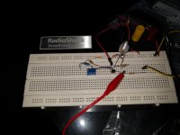
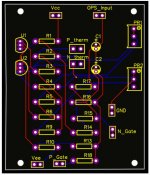
So, the bias circuit is on a breadboard so that I can figure out how the TL431 works and how the thermistor fits into the 431 circuit. That is working in a use-what-is-on-the-shelf manner. The first thing I grabbed was a bag of 10k resistors.
For the N-channel puck, the cold Vgs will be around 4.15V. Warming up the thermistor drops the bias voltage. Bingo. It works in principle. It will need tweaks once the puck is powered and runs up to temperature.
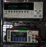
The bias circuit is fed by a 10K resistor that is powered at 24V. The bias circuit draws 2mA.
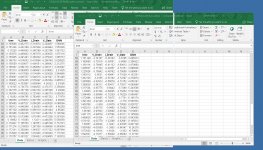
I played with the TL431 and found that around 1/2 mA is required to flow through the TL431 before the 2.5V ref becomes stable. Below 1/2 mA, the ref voltage droops. There is range of current flow where the ref voltage increases with increasing current and a point where the ref voltage remains relatively stable with increasing current.
For this particular build, the resistors chosen make the 431 ref voltage very stable with changes in the 24v rail.
This project has sat idle most of the last 12 months as a super busy 2018 work schedule consumed me.
So, the bias circuit is on a breadboard so that I can figure out how the TL431 works and how the thermistor fits into the 431 circuit. That is working in a use-what-is-on-the-shelf manner. The first thing I grabbed was a bag of 10k resistors.
For the N-channel puck, the cold Vgs will be around 4.15V. Warming up the thermistor drops the bias voltage. Bingo. It works in principle. It will need tweaks once the puck is powered and runs up to temperature.
The bias circuit is fed by a 10K resistor that is powered at 24V. The bias circuit draws 2mA.
I played with the TL431 and found that around 1/2 mA is required to flow through the TL431 before the 2.5V ref becomes stable. Below 1/2 mA, the ref voltage droops. There is range of current flow where the ref voltage increases with increasing current and a point where the ref voltage remains relatively stable with increasing current.
For this particular build, the resistors chosen make the 431 ref voltage very stable with changes in the 24v rail.
Attachments
giving nice dominant 2nd, when all is done
Agreed. I read through this thread carefully twice and saw that lower gm N-channel puck is desired.
This particular pair of pucks will be able to sustain 210 amps on the P side and 660 amps continuous on the N side per the datasheets.
I would be long gone from room , prior to them conducting that much
Special amp for special purpose. I will have the only one on my street.
- Home
- Amplifiers
- Pass Labs
- F4 Beast Builders