Yes, i will try it.
Lhquam already told that you have to overwhelm a lot of pos k2 phase to come in the neg region.
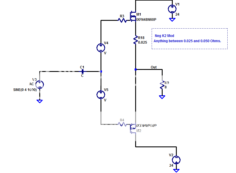
A small amount of resistance at the source of the N Channel part completely converts the part, so that neg K2 is easily achieved. Think about what is happening and it will become obvious. Don't succumb to the evil brain fart atttack. Hahaha
If you try and achieve it via the front end then yes you have to overwhelm it, but the method I described is super effective in this specific situation.
Have a little faith baby.

Eg Adding 50 mOhms to a 10 Siemens part converts it to something resembling a 7 Siemens part (approximately, I don't like decimal places
)A little resistance at the source goes a very long way.
Last edited:
Last edited:
May be the title of the thread might be bit irritating. "F4 Beast" was chosen I suppose because the IXYs might do the same what the three pairs in F4 did and they are both common drain. And "F4 beast" is also used because we do the biasing in a very similar way Nelson showed in the F4.
Of course there is a frontend driving the F4 beast and there is also unlike F4 current feedback.
We do not care much for the "real" XA25 circuit, it is more the fun using the monster parts and using what Nelson showed us already.
Besides this I suppose that the real XA25 is not so very very different.
I think that Lhquam with his abilities and his analytic mind will be closer or will get closer to the "real" circuit.
Meanwhile we have fun and hear what we can build....
Or don't we brother 2picodumbs?
:--))
Is there a bit of a non sequitur between the XA25 and this design? I mean, the XA25 has gain. So, the similarity is just the output devices (which are yet unknown) and a desire for a similar topology without gain (or bring your own front end?)
I don't want to be promoting cloning Pass Labs IP except where Papa has given general information to help us build an amp that closely resembles it's performance, hence the reason for naming it completely different to XA25.
Besides that, cloning an amp is bloody boring.
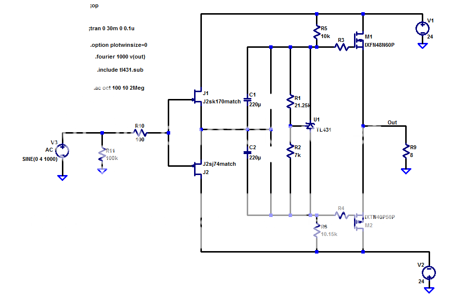
Both Generg and I have provided front end circuits when mated with the output stage produces performance that is in the same ball park of the XA25.
You are welcome to copy the front end circuits already provided or come up with your own to produce the performance specs Papa has freely given us, or take it in any direction you choose.
I want to encourage people to build from their own creative ideas.
Papa has been teaching us to do this for a long time and already provided us with enough building blocks to have fun. It would be somewhat of a waste not to use what he has already given us.
If you run the jfets without source resistance like in F6 then I believe it might work.I am all for a new version of the F4
It would not take long to find out.
The capacitance in the windings of the Jensen Transformer used in the F6 is also high. It's worth trying it out.
So, the similarity is just the output devices (which are yet unknown) and a desire for a similar topology without gain (or bring your own front end?)
The devices are very easily narrowed down, due to the number of P Channel devices that are offered in an SOT-227 package.
Once you've determined that, it's just a matter of choosing a reasonable matching N Channel device.
The IXYS parts provided in the first post do the job.
Last edited:
.......
The capacitance in the windings of the Jensen Transformer used in the F6 is also high.........
is it variable , voltage vise ?

however , driving 6CA7 wit 12AX7 never was my thing , except in case when I'm rejuvenating olde drek and leaving it as is
is it variable , voltage vise ?
however , driving 6CA7 wit 12AX7 never was my thing , except in case when I'm rejuvenating olde drek and leaving it as is
Your understanding of transformers is far greater than mine. You could certainly enlighten me on that.
If you look at the Ciss curves for those IXYS Polar devices, they are very flat (much better than IR devices).
If extra current might be required out of those jfets we could go with 16mA parts and add cascodes to keep the dissipation under control.
Output impedance of jfet front end certainly won't be a problem.
What do you say Zen Mod? Worth a try?
Last edited:
you know , I grew up (literally) on all sorts of bicycles
during that time , I pretty well learned what falling off/down means and how it feels
so , no need of reminding how's that
so , why bother driving them (pucks) in wimpy way ?
as I said - when you once heard how anemic and lacking in highs driving 6CA7 with 12AX7 is , you heard enough for entire living
so , ensure 30mA or more in stage preceding pucks , one puzzle placed where it belongs
be it Mini F5 (with preputium made of Toshiba mosfets in output) ,or BA3FE or Papa's Sony FE , or just buffer in front ..... be aware of fact that we are often falling in same trap , when speaking of buffers
one thing is Rout , completely other thing is output current capacity
say 2SJ74/2SK170 buffer - pretty low Rout ...... and , unfortunately, pretty low output current capacity
ya remember mosfet craze , when Toshiba made T03 cans ?
everyone was making amps and kits with them , and I believe best selling ones where Brit-made dreks - Iq in range of 10mA, mosfets driven to full swing with tiny T092 buggers ......
https://youtu.be/4vuW6tQ0218
Last edited:
Do not forget the required voltage swing for +/-20V for 25W into an 8 Ohm load. You could implement a cascode that keeps the JFET Vds at around 5V but it will require either higher rail voltages or voltage bootstrap tricks like used in the F4 to get enough voltage for the drain or collector of the cascode device.
Last edited:
so , why bother driving them (pucks) in wimpy way ?
There is your answer luvdunhill, just drive it directly from your front end circuit and forget the jfets, provided you have a nice low output impedance and 35mA push pull or 70mA single ended from your preamp, you don't need to add global feedback, if you don't want to.
Otherwise feel free to use the circuits already suggested in post 1 or Generg's circuit, or make something else.
Last edited:
I fell victim to the Evil Brain Fart Monster.Do not forget the required voltage swing for +/-20V for 25W into an 8 Ohm load.
Hahahaha
- Home
- Amplifiers
- Pass Labs
- F4 Beast Builders