Well done, man!

Just thinking about the thermistor, we could possibly bolt that thing straight into the extra source pin for almost lag free thermal tracking, just haven't decided whether the thermal lag is desirable or not.
I might try it both ways.
Last edited:
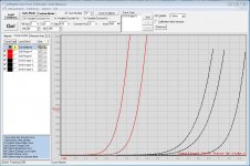
Also based on the measurements performed at 22.1C and 52.7C it appears a difference of 0.1V between cold and hot is all that is required in the biasing circuit for 40P50P.
So maybe a 0.2V difference in the biasing circuit between cold and hot across the pair of 48N60P/40P50P will be adequate.
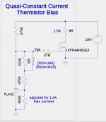
The middle circuit in post #17 http://www.diyaudio.com/forums/pass-labs/300233-f4-beast-builders-2.html#post4909046 provides nearly constant current from the fet. The resistors must be matched to the Vgs vs. temperature curve and thermistor. The system of equations is fairly simple, but difficult to express in closed form.
Just thinking about the thermistor, we could possibly bolt that thing straight into the extra source pin for almost lag free thermal tracking, just haven't decided whether the thermal lag is desirable or not.
I might try it both ways.
Clever idea:
Attachments
The middle circuit in post #17 http://www.diyaudio.com/forums/pass-labs/300233-f4-beast-builders-2.html#post4909046 provides nearly constant current from the fet. The resistors must be matched to the Vgs vs. temperature curve and thermistor. The system of equations is fairly simple, but difficult to express in closed form.
Yeah basic stuff, but has that been experimentally verified?
I was under the impression it was simulated results.
Edit: Still deciding whether I want a subtle improvement or almost robotic control, I sometimes think going in half measures is better than trying to reach perfection. Have to let the brain think about it more, I see both pros and cons.
Last edited:
Clever idea:
Still deciding whether I actually want that though.
I'll need to observe it first.
Yeah basic stuff, but has that been experimentally verified?
I was under the impression it was simulated results.
Edit: Still deciding whether I want a subtle improvement or almost robotic control, I sometimes think going in half measures is better than trying to reach perfection. Have to let the brain think about it more, I see both pros and cons.
I should be able to breadboard that circuit and test it in my measurement setup. I will start with a cold heatsink, adjust for nominal bias current, and allow the heatsink to heat up to over 50C making measurements of the bias current.
I should be able to breadboard that circuit and test it in my measurement setup. I will start with a cold heatsink, adjust for nominal bias current, and allow the heatsink to heat up to over 50C making measurements of the bias current.
That would be great.

What I would like to avoid is where it might possibly overshoot the bias point when cold eg 2.3A, then drop back down to the bias point of 2A when hot.
I think I would like to maintain some of the original thermal characteristic of the device eg maybe 1.9A when cold and 2A when hot.
Last edited:
Measured 3 IXFN48N60P devices (2 more to go)
At Id=2A I'm getting 6.3S, 6.6S and 6.8S
close enough to my liking , to other one
That would be great.
What I would like to avoid is where it might possibly overshoot the bias point when cold eg 2.3A, then drop back down to the bias point of 2A when hot.
I think I would like to maintain some of the original thermal characteristic of the device eg maybe 1.9A when cold and 2A when hot.
That can be done, but why not keep it constant from cold to hot?
That can be done, but why not keep it constant from cold to hot?
I'm not entirely against the idea, show me a video of it and you might convince me.
Just thinking how this might change the AC sine wave when the device is oscillating between 0A and 4A at around 20Hz to 80Hz.
I would want to see the sine wave on a CRO with and without the thermal compensation circuit. Just thinking what happens when the device is drawing significantly more or less current eg around 20Hz to 80Hz.
Do we want the thermistor to perfectly thermally track the AC signal (will the biasing circuit operate linearly over a wide range of AC current when the thermistor is added) or do we want the thermistor to be blind to the AC signal? Do we want the thermistor to have enough thermal lag that it isn't affected by the AC signal?
Just thoughts.
This is why I tend to like the cave man approach. Less for my brain to think about. Hahahaha
Last edited:
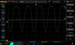
The thermal time constant of the thermistor and the mass FET case and heatsink should be quite long compared to 20Hz. I can do a test right now: a 20Hz signal, approximately 0A to 3A into an 8R load with Vds at 24V quiescent, and look for any AC signal on the thermistor output.
Here is the "thermistor thermal modulation test". The R25=10K thermistor is mounted to the unused source terminal as shown in post #223. One end is connected to ground, the other end thru a 20K resistor to a clean power supply at +15V. The fet is driving an 8R load connected to +36V. The CH1 trace shows the voltage on the FET Drain pin. The current ranges from about 0A to over 3A. The CH2 trace shows the AC voltage across the thermistor. Nothing detectable. The DC voltage is around 2V.
Attachments
A good year 2017 for you all!
I hope you creeped all well in 2017.......
is 1917 really already 100 years ago? Unbelievable ....!
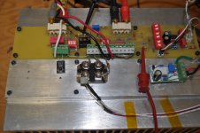
I installed the 48NP60 and the 40P50P instead of the old puck ones.
First I was afraid that I could get a bit difficult because the Vgs threshold of the new N and P pucks were very different and different from the values Nelson showed in the BAF2016 talk.
Look at the picture...I could not order more... no money end of the year as always....
But all went fine, I could adjust both channels without difficulties to 1.5A.
I played a bit with the feedback. The OLH with the 1k load was about 40dB and with a 2k feedback resistor and a CLG of 23dB I liked the sound more than with 1k and 4k7 feedback resistors. Of course very subjective and I will do again the final comparison with the Aleph 3 and the Klipschorns at my friends house.
Hope the battle will be more equal....
Back to the possibility to make a single ended Amp out of it for a certain wattage let us say up to five Watt by adding a 125R Dale resistor as CCS.
But on the neg or on the pos rail side? What is the right side for the wanted neg k2 phase.
I go to Spice and try to find the answer, but Spice and phase representation is too often irritating for me.
Is any mastermind or simple mind like my brother 2picodump here, who could give an answer.....
I hope you creeped all well in 2017.......
is 1917 really already 100 years ago? Unbelievable ....!
I installed the 48NP60 and the 40P50P instead of the old puck ones.
First I was afraid that I could get a bit difficult because the Vgs threshold of the new N and P pucks were very different and different from the values Nelson showed in the BAF2016 talk.
Look at the picture...I could not order more... no money end of the year as always....
But all went fine, I could adjust both channels without difficulties to 1.5A.
I played a bit with the feedback. The OLH with the 1k load was about 40dB and with a 2k feedback resistor and a CLG of 23dB I liked the sound more than with 1k and 4k7 feedback resistors. Of course very subjective and I will do again the final comparison with the Aleph 3 and the Klipschorns at my friends house.
Hope the battle will be more equal....
Back to the possibility to make a single ended Amp out of it for a certain wattage let us say up to five Watt by adding a 125R Dale resistor as CCS.
But on the neg or on the pos rail side? What is the right side for the wanted neg k2 phase.
I go to Spice and try to find the answer, but Spice and phase representation is too often irritating for me.
Is any mastermind or simple mind like my brother 2picodump here, who could give an answer.....
Attachments
Back to the possibility to make a single ended Amp out of it for a certain wattage let us say up to five Watt by adding a 125R Dale resistor as CCS.
But on the neg or on the pos rail side? What is the right side for the wanted neg k2 phase.
I'd guess on the positive rail so that the P channel part would operate at a higher current than the N channel part, possibly allowing for negative phase second harmonic (provided the SE bias is high enough to get us into a situation where the P channel part exhibits more transconductance than the N channel part).
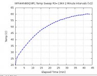
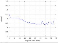
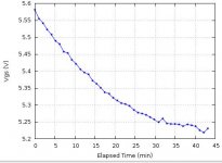
Here are some results from a quasi-constant bias current circuit. The plots show Temperature vs. time, Isen (bias current) vs. time, and Vgs vs. Temperature. The heatsink started cold at around 20C and was heated by the FET unser test, and an additional FET dissipating about 100W additional. The bias current drops about 3% from 25C to 50C. The slope of the Vgs vs. Temperature curve is very sensitive to the resistor values in network around the TL431.
Attachments
Last edited:
- Home
- Amplifiers
- Pass Labs
- F4 Beast Builders