Techno-nuances.
Here are additional details/analyses of the audio system/schematic [attached again] of the previous post.
1. It accepts two loudspeakers [twins] one across each coil for more and easy output power. When the extent of positive feedback equals that of negative feedback [R6 = 3.6K = (R12+R13)] one gets a stable mono reproduction with the vocals smack between the two loudspeakers.
2. When the extent of negative feedback from Vout to the gates of the FETs is decreased by lowering the value of [R12+R13] relative to R6 = 3.6K, center stage moves towards the loudspeaker which is connected to Coil#2.
3. The voltage drop across Coil #2 increases at a rate which is ~10 fold that of the voltage across Coil #1 due to a consequent decrease of negative feedback to the gates of the FETs. The voltage drop across Coil #1 stays ~put [no loss in volume!]; it is the much larger voltage drop across Coil #2 which causes its attached loudspeaker to be louder and still sound quite clean.
4. Can easily listen to one loudspeaker only inside the room and preferably in a corner. The loudspeaker can be attached to either Coil; with the attachment to Coil #2 way preferred. Because it has more power output relative to that of Coil #1 and because this power output continues to increase with increasing positive feedback; meaning by relatively decreasing negative feedback to/in the system.
5. I am using a generic [SONY] VSA which has an internal overall negative loop feedback. Its system unexpectedly sounds great. I also use an industry standard which is Threshold S/150 that lacks an internal overall negative loop feedback. Its system sounds superb. This audio system approach is versatile as it accepts any VSA.
6. The joint drain current of the FETs flows through Coil#2 in a closed loop outside common. It induces a current in Coil#1 which is in-phase with that delivered by VSA in Coil#1. This is a clear case of bootstrapping VSA and possibly endowing it with Positive Current Feedback [PCF].
7. The music emanating from the loudspeaker [every which way used] sounds like it is is driven by a voltage source amp.
8. And a future post for the case of an audio system using a Dual Voice Coil subwoofer.
Best
Anton
Attachments
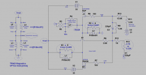
The application of the attached schematic shows a power toroid [TRIAD] generating a high voltage out music signal [High Vout]. It is possible with the appropriate transformer to drive an electrostatic loudspeaker. This arrangement differs from others in that High Vout incorporates or is infused with positive current feedback as was discussed in preceding posts.
1. Voltage Source Amp [VSA] drives the toroid's secondary #1 [Sec. #1].
2. The FETs of DEF drive the toroid's secondary #2 [Sec. #2].
3. A combination of positive and negative feedback are inherent in this system. The extent of positive feedback is adjustable in its favor by minimizing the sum of resistors R12 and R13 as was mentioned in the previous post.
Best
Anton
Attachments
An audio system using a dual voice coil subwoofer
The attached schematic has [mostly] appeared in previous post #301. This one is for an audio system using a dual voice coil [DVC] subwoofer . This sub sits in the corner of the listening room. It has an internal dual crossover. Each voice coil, and its crossover are electrically separate from the other similar combination.
I loaded each high pass output with an 8 Ohm non-inductive power resistor so as to do the following four experiments. Their graphical results are attached. Please consult the schematic.
1. A sine signal generator spanning the frequency range of 30 to 150 Hz drives the voltage source amp [VSA] which is the R channel of a Threshold S/150 power amp.
2. Two key variables were used. Use the TRIAD transformer or not and vary the system's ratio of the extent of positive to negative feedback. This was done by changing the value of Rf = R12 +R13 in the schematic . The chosen Rf values were either 3.7K for the two baseline experiments or 1.2K for a higher extent of Pos. to Neg. feedback ratio.
3. The two baseline experiments with and without TRIAD at a fixed Rf = 3.7K are below the black horizontal line at the ordinate [Y axis] value of Ratio = 1.5.
4. The top part of the graph defines this resultant Ratio = [Vout-Vload]/ Vload. This Ratio is a voltage gain due to increased positive feedback.
5. The two graph using dots only show the effect of increased voltage gain [essentially Vout] due to an increased positive feedback in the absence of the TRIAD transformer. The DVC and its magnet structure is the transformer implicated here.
6. Ditto as in point 5 with the TRIAD [encircled dots] used to augment the inherent transformer of the DVC-magnet structure .
7. Note the relative loss of Ratio [aka gain] when TRIAD is used; albeit with the benefit of its presence generating a smooth graph by comparison.
The verdict from the 4 experiments maybe:
1. No need to use an external augmenting transformer [e.g. TRIAD]. The internal DVC-magnet transformer is fully adequate in this application. The added benefit of simplicity and maximum system gain are evident.
2. The effect of an added transformer and some extent of positive feedback is expected to benefit the destruction of standing waves in the room corners.
3. The broad frequency performance of an added transformer [namely TRIAD] may or not be beneficial for the high pass component music. It will add to it.
I will listen to this system with and without TRIAD at Rf =1.2K for best likability.
Best
Anton
Attachments
Another sound system...
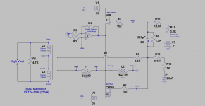
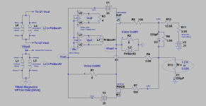
The attached schematic is for another audio system which I am listening to. It is stable against oscillation and sounds great. It is along the same lines of thought/approach which I have been using todate. Please note its building blocks:
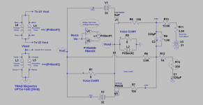
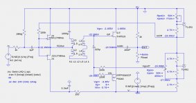
1. TRIAD Magnetics VPT24-1040 power toroid. It has 2 independent secondary windings [12 Vac]. They are used as a 1:1 isolation power transformer for music. The color-coded wiring of this transformer is depicted at the far left of the schematic.
2. A Bridge-Tied-Load [BTL] PYRAMID PB440X] voltage source amp. It is a car audio power amp. Its drives the one [PriSec#1] winding of TRIAD. The second [PriSec#2] winding of TRIAD drives the joined sources of the DEF FETs.
3. BTL and its toroid isolation power transformer can also be a vacuum tube [VT] power amp. The VT's power output winding will similarly couple to the joined sources of the FETs.
4. A dual voice coil [DVC] subwoofer plus satellites as discussed in previous posts. This full-range loudspeaker assembly sits in the corner1 of the listening room. I sit at the diagonal [opposing] corner2 or along the corner1-corner2 diagonal.
5. Old faithful DEF. Its FETs are configured in common gate and common source configurations so as to manipulate its positive and negative feedback [value of R13].
6. The DVC magnet assembly generate positive feedback.
Best
Anton
The attached schematic is for another audio system which I am listening to. It is stable against oscillation and sounds great. It is along the same lines of thought/approach which I have been using todate. Please note its building blocks:
1. TRIAD Magnetics VPT24-1040 power toroid. It has 2 independent secondary windings [12 Vac]. They are used as a 1:1 isolation power transformer for music. The color-coded wiring of this transformer is depicted at the far left of the schematic.
2. A Bridge-Tied-Load [BTL] PYRAMID PB440X] voltage source amp. It is a car audio power amp. Its drives the one [PriSec#1] winding of TRIAD. The second [PriSec#2] winding of TRIAD drives the joined sources of the DEF FETs.
3. BTL and its toroid isolation power transformer can also be a vacuum tube [VT] power amp. The VT's power output winding will similarly couple to the joined sources of the FETs.
4. A dual voice coil [DVC] subwoofer plus satellites as discussed in previous posts. This full-range loudspeaker assembly sits in the corner1 of the listening room. I sit at the diagonal [opposing] corner2 or along the corner1-corner2 diagonal.
5. Old faithful DEF. Its FETs are configured in common gate and common source configurations so as to manipulate its positive and negative feedback [value of R13].
6. The DVC magnet assembly generate positive feedback.
Best
Anton
Attachments
An objective performance of the subwoofer ....in room corner
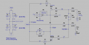
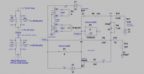
I put the dual voice coil [DVC] subwoofer in the corner of the listening room so as to allow its [woofer] cone to experience all forces of motion to include those of standing waves. The attached graph depicts an objective performance of this DVC subwoofer in the frequency range of 30 to 150 Hz. Also shown is an updated schematic of the power amp of the previous post for this objective experiment. Please note the following encircled labels for voltage, and use the previous post for background:
1. Vout. The power output at the opposed drains of the DEF's FETs. It is a current source port.
2. Vload. The voltage at the joined sources of the DEF's FETs. It is the voltage drop across Voice Coil #1 and/or also that induced by the TRIAD isolation [1 PriSec#1 : 1 Prisec#2] transformer which is driven by the Right Channel of the BTL Pyramid power amp.
3. The difference between Vout and Vload: [Vout -Vload] is the voltage drop across Voice Coil #2. The current which flows through this voice coil #2 circulates only through the drain-source channels of both FETs.
4. Vref. The R and L inputs of Pyramid are driven by the same Vin AC signal as seen in the attached schematic. The BTL power output of the Left channel is loaded with an 8 Ohm non-inductive power resistor. It floats and is used only to generate reference results. Vref is the voltage drop result across this load resistor.
5. Vpri. The voltage drop across the Pyramid Right channel BTL power outputs which drives the TRIAD's PriSec#1 winding.
To the graphs. The ordinate [Y axis] is a Calculated Voltage which uses simple ratios of the encircled above Voltage results as a function of frequency [30 -50 Hz.]
A. The ratio of Vref to Vpri is a flat line [triangle data] of slope = zero at a Calculated Voltage equal to 1. It says that both channels of Pyramid are matched!
B. The ratio of [Vout -Vload]/Vload or [Vvoice coil #2 divided by Vvoice coil#1] is the upper most graph using data dots only. It is the normalized gain of the current source amp due to the DEF FETs. A value greater than 1 signals voltage gain.
C. The ratio of [Vout-Vload]/Vpri or [Vvoice coil#2 divided by Vpri ] is the graph of circles which encircle results' dots. This graph references the gain of the DEF FETs to that of the Right Channel of the BTL output. It has a minimum value [1.35] at the woofer's resonance frequency of 80 Hz. This graph is/looks like the inverted impedance curve of a woofer. It is normally generated by driving the woofer's voice coil with a current source amp which is the case here.
D. The ratio of [Vload to Vpri] is the graph of square results mostly below the Calculate Voltage equal to 1. It is the voltage ratio the voltage values on the TRIAD 1: 1 isolation transformer windings. I do not understand the reasons behind the deviation from the expected 1:1 ratio!
Next post will show results like the above with a Class T BTL amp so as to extend the scope this application.
Best
Anton
Attachments
An audio system using a Class T digital amp...
The Stellar Labs Stereo Class T Digital power amp [15W/ch; sold by MCM Electronics] most probably uses the acclaimed Tripath chip named TA2020-020. Its outputs are bridge-tied-load [BTL] like that of PYRAMID which uses instead a TOSHIBA bipolar power opamp chip named TA8220H. The architecture of both power amps are radically different; warranting a [comparative] objective performance experiment. How's one begin to describe the influence of bootstrapping and Positive Current Feedback [PCF] on the internal operation of Class T or Class D in general?
The schematic of the prototype power amp on the bench and the resultant performance graphs are attached. The details of this experiment are exactly like those in the previous post. The relevant differences are:
1. The load to the left channel is a 4 Ohm power resistor [instead of 8] used to generate Vref.
2. The graphs are similar in shape to those generated by PYRAMID under similar test conditions. However they are not as smooth. This difference [as nice curves] is evident in the frequency range of 80 to 150 Hz for Stellar and appears linear! I am using the same axes scale for the graphs I have generated todate. One can superimpose printouts for the graphs due to Threshold S/150, PYRAMID, and Stellar for visual comparison.
3. The general objective observations and conclusions declared in the previous post for PYRAMID apply equally to Stellar.
4. I liked the sound due to PYRAMID. I'll listen to Stellar and report.
5. It follows from the above that the architecture of the BTL power amp [meaning digital Class T versus analog Class AB] may or may not affect the objective performance I went after. I'll hear about any possible impact on subjective performance by corner listening.
Got more objective experiments to do and report.
Best
Anton
Attachments
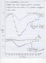
A Visual on the Effect of Positive Feedback and Consequent Bootstrapping
I listened to the audio system [put in room corner] which I described in the previous post. It uses the Class T BTL amp by Stellar Labs. Its sound is fully satisfactory; noting that my listening location was at its opposite corner and anywhere along the diagonal connecting both corners.
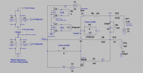
Please take a look at the attached schematic of this experiment. It is exactly the same as the one shown in the previous post. Note the encircled resistor [Rf] at its bottom right. Its value can either be [1.2K] which the reference value I used [for experiments and music to date] in the previous post or [0.32K].
1. The magnitude of the negative feedback voltage generated at the gates of the DEF Fets is determined by this equation ~{Vf = Vout [Rf/(Rf+3.6K)]}; discounting the parallel values of the bias resistors which will make it exact.
2. The value of 0.32K in the equation gives a low [Vf] relative that using [Rf=1.2K].
3. This DEF circuit has an intrinsic and simultaneous positive and negative feedback. This attribute is its forte.
4. It follows that the ratio of positive to negative feedback was increased by using an Rf = 0.32K relative to that using Rf = 1.2K.
5. The three scanned documents declare an objective performance of this audio system. Again, the DVC subwoofer and its satellites sat in the corner.
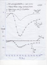
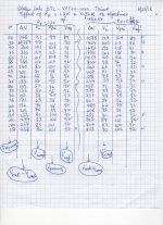
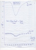
5a. One scanned document shows the tabulated data I collected. The AC measurements were done with an AC multi-meter. They correspond to the circled voltages in the schematic.
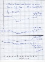
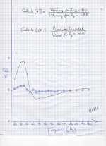
5b. A second scanned document is entitled "Effect of Rf". This graph shows the tremendous effect of the increased extent of positive feedback [for Rf = 0.32K] and its consequent bootstrapping. Note the key results [Calc. V]. It is the ratio of the voltage across Voice Coil # 2 driven by the DEF Fets relative to that across Voice coil #1 which is driven by the Class T BTL amp.
5c. In this third scanned document, this graph shows the on-goings at the primary winding of the TRIAD as a function of Rf. It shows bass boost in both cases below the 80 Hz resonance frequency of the woofer. I was also looking for evidence of bootstrapping!
The DEF topology as envisioned by Mr. Pass is simple and ingenious. These past posts essentially broaden its primary use in actual DIY audio systems in real listening rooms. Most probably I'll find more applications.
Best
Anton
I listened to the audio system [put in room corner] which I described in the previous post. It uses the Class T BTL amp by Stellar Labs. Its sound is fully satisfactory; noting that my listening location was at its opposite corner and anywhere along the diagonal connecting both corners.
Please take a look at the attached schematic of this experiment. It is exactly the same as the one shown in the previous post. Note the encircled resistor [Rf] at its bottom right. Its value can either be [1.2K] which the reference value I used [for experiments and music to date] in the previous post or [0.32K].
1. The magnitude of the negative feedback voltage generated at the gates of the DEF Fets is determined by this equation ~{Vf = Vout [Rf/(Rf+3.6K)]}; discounting the parallel values of the bias resistors which will make it exact.
2. The value of 0.32K in the equation gives a low [Vf] relative that using [Rf=1.2K].
3. This DEF circuit has an intrinsic and simultaneous positive and negative feedback. This attribute is its forte.
4. It follows that the ratio of positive to negative feedback was increased by using an Rf = 0.32K relative to that using Rf = 1.2K.
5. The three scanned documents declare an objective performance of this audio system. Again, the DVC subwoofer and its satellites sat in the corner.
5a. One scanned document shows the tabulated data I collected. The AC measurements were done with an AC multi-meter. They correspond to the circled voltages in the schematic.
5b. A second scanned document is entitled "Effect of Rf". This graph shows the tremendous effect of the increased extent of positive feedback [for Rf = 0.32K] and its consequent bootstrapping. Note the key results [Calc. V]. It is the ratio of the voltage across Voice Coil # 2 driven by the DEF Fets relative to that across Voice coil #1 which is driven by the Class T BTL amp.
5c. In this third scanned document, this graph shows the on-goings at the primary winding of the TRIAD as a function of Rf. It shows bass boost in both cases below the 80 Hz resonance frequency of the woofer. I was also looking for evidence of bootstrapping!
The DEF topology as envisioned by Mr. Pass is simple and ingenious. These past posts essentially broaden its primary use in actual DIY audio systems in real listening rooms. Most probably I'll find more applications.
Best
Anton
Attachments


An important parallel..
This may be a relevant connection regarding the operation of the amp I described in the previous post. Please consult the same attached schematic and the graph. I see the following parallel with a Constant Voltage and Constant Current power amp as described by Mr. Pass in his Patent US, 4,107,619. His patent gave the commercial Threshold STASIS power amps.
1. The experimental amp is a combination of a voltage source amp [VSA] which is Class T, and a Current Source Amp [CSA] which is the complementary FETs in DEF.
2. Both VSA and CSA amps collaborate towards the power and sound outputs. Most of this power [and sound] outputs emanate from CSA as the attached graph shows. The evidence is the high ratio of the voltage across voice coil #2 [from CSA] relative to that across voice coil #1 from Class T BTL at either value for Rf. A ratio of 9 [for example] in the upper graph is like the current gain [Hfe]; as both coils has similar values of impedance.
3. At normal listening levels, the contribution to sound pressure of CSA is dominant. Thus VSA operates at a pseudo Constant Voltage; meaning [note that Class T is not cascoded] the change in the Vds of its output Mosfets is a small fraction of +Vcc =12Vdc.
4. The Class T VSA current output is also low into the load [voice coil #1] for 2 reasons: First it is bootstrapped [see point 5], and second the current output of CSA is dominant towards sound pressure.
5. Let's talk bootstrapping. I see it as positive current feedback [PCF]. It is not mediated by a galvanic connection in my example prototype amp. Instead, it is electromagnetic; meaning enabled by the transformer action inherent in the dual voice coil / magnet structure of the woofer.
5a. The current moving through voice coil #2 circulates only in the DEF FETs. Because the PSUs of the FETs are not connected to common. Voice coil #2 induces a current in voice coil #1 as the principal bootstrap current, and avenue for PCF.
I'll listen to the amp at the Rf =0.32K [high PCF] and report.
Best
Anton
Attachments
Another Potential DEF Application
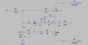
The recent schematics I posted in Zen Mod's thread "Most Greedy Boy..Koans" birthed the attached [concept] schematic. Where to post? I chose this thread.
PNP is connected in a common base configuration. It is used to induce positive current feedback therein DEF, and thus raise its input impedance c/o bootstrapping.
The inclusion of C1 in this schematic has two possible connections as shown by the Test Switch.
I hope there's value for this concept schematic in DEF, DEFiSit and in Zen Mod's technical approaches..
Best
Anton
Attachments
can you share asc file here ?
just to check few things ......
TIA
Hi ZM. The attached .asc file does not have language to run it. I only used Spice to write it. I hope it helps.
Best
Anton
Attachments
DEF and DEFiSIt continue to be hot topics in the Pass Labs Forum. I have a DEF prototype amp on the bench. I named it Old Faithful. It brings a lot of fun via experimentation.
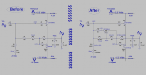
The attached shows two schematics. They are actual DEF prototypes. The one shown to the right of the $-signs vertical barrier is the newest. It uses a general method to experiment with a pair of FEts in DEF or DEFiSIT which have an intrinsic large difference in their Vgs values.
The schematic to the left of the $-signs vertical barrier [Before] is my original DEF amp.
1. It is a textbook Pass design. It uses his [generous] advice to use a resistor string so as to bias each FET to its individual and [intrinsic] Vgs at the idle conditions. Works and sounds great as it is also accurate and precise.
2. The biasing resistor [~1K] bridges the two gates of the DEF FETs.
3. The measured voltage drop across said resistor is ~ 1Vdc. This voltage drop is expected to be higher in a DEFiSIT [e.g. using 2SK82] by using the same biasing scheme.
4. Thus the resultant value of the Vgs-bridging resistor will also be higher than 1 KOhm. It may affect the slew rate of P-MOSFET; because the input signal [Vin] is directly in series with its input capacitance.
5. Please ignore the PSU rails of Old Faithful. These DEF amps are part of other [fun] experiments in my Class aP amplification thread. I am operating Old Faithful room- temperature cold.
Here's the description of the Right schematic of the new prototype DEF amp [After]:
1. Delta Vgs of FETs is ~1 V.
2. It is fully adequate therein to use an NPN Germanium [2N1306]; but not a Silicon-based.
3. NPN is used in the common base configuration. It idles at 1 mA [choice]. It is an important part and parcel of the bias scheme to generate the [same] correct Vgs values as those in the parent [left schematic].
4. NPN directly injects [Vin] into the gate of P-MOSFET. NPN's output impedance is intrinsically high [common base]. It is also rendered even way higher therein because the AC voltage drop across its load resistor [1.8 K] is ~zero [in-phase bootstrapping].
5. I am suspicious that NPN operates at a constant collector current and at a constant Vce.
Does this new arrangement impact objective performance? The Newest Old Faithful DEF amp is stable [against oscillation] and sounds superb.
Best
Anton
Attachments

Hi Antoinel, I agree. The DEF on the left of the diagram is a superb amplifier. This is the THD that I measured months ago ( UJN1208K - IRFP9240 ). The amp had bootstrap capacitor in addition.DEF and DEFiSIt continue to be hot topics in the Pass Labs Forum. I have a DEF prototype amp on the bench. I named it Old Faithful. It brings a lot of fun via experimentation.
The attached shows two schematics. They are actual DEF prototypes. The one shown to the right of the $-signs vertical barrier is the newest. It uses a general method to experiment with a pair of FEts in DEF or DEFiSIT which have an intrinsic large difference in their Vgs values.
The schematic to the left of the $-signs vertical barrier [Before] is my original DEF amp.
1. It is a textbook Pass design. It uses his [generous] advice to use a resistor string so as to bias each FET to its individual and [intrinsic] Vgs at the idle conditions. Works and sounds great as it is also accurate and precise.
2. The biasing resistor [~1K] bridges the two gates of the DEF FETs.
3. The measured voltage drop across said resistor is ~ 1Vdc. This voltage drop is expected to be higher in a DEFiSIT [e.g. using 2SK82] by using the same biasing scheme.
4. Thus the resultant value of the Vgs-bridging resistor will also be higher than 1 KOhm. It may affect the slew rate of P-MOSFET; because the input signal [Vin] is directly in series with its input capacitance.
5. Please ignore the PSU rails of Old Faithful. These DEF amps are part of other [fun] experiments in my Class aP amplification thread. I am operating Old Faithful room- temperature cold.
Here's the description of the Right schematic of the new prototype DEF amp [After]:
1. Delta Vgs of FETs is ~1 V.
2. It is fully adequate therein to use an NPN Germanium [2N1306]; but not a Silicon-based.
3. NPN is used in the common base configuration. It idles at 1 mA [choice]. It is an important part and parcel of the bias scheme to generate the [same] correct Vgs values as those in the parent [left schematic].
4. NPN directly injects [Vin] into the gate of P-MOSFET. NPN's output impedance is intrinsically high [common base]. It is also rendered even way higher therein because the AC voltage drop across its load resistor [1.8 K] is ~zero [in-phase bootstrapping].
5. I am suspicious that NPN operates at a constant collector current and at a constant Vce.
Does this new arrangement impact objective performance? The Newest Old Faithful DEF amp is stable [against oscillation] and sounds superb.
Best
Anton
View attachment 694571
Now this a DEF prototype on the bench ( better on the floor )
View attachment 694572
The UJN1208K and the IRFP9240 have the same Vgs. There is no resistors string and bootstrap capacitor. In DC the amp is stable even after the torture of the hair dryer ( 1.3A @ +/-24V ). In AC the current is slightly lower but unforyunately, under the same conditions, the THD is higher. The sine wave is clearly deformed. In the next experiments will place the resistors string and the IRFP of the first prototype. An interesting variant will also be the constant current source ( #118 ).


- Home
- Amplifiers
- Pass Labs
- DEF Amp